Slide bearing

a technology bearings, which is applied in the direction of sliding contact bearings, connecting rod bearings, machines/engines, etc., can solve the problems of high possibility of damaging the crank bearing or the bearing supporting the connecting rod, and achieve the effect of reducing the amount of lubrican

Active Publication Date: 2010-02-25
TOYOTA JIDOSHA KK
View PDF6 Cites 37 Cited by
  • Summary
  • Abstract
  • Description
  • Claims
  • Application Information

AI Technical Summary

Benefits of technology

[0005]Accordingly, it is an objective of the present invention to provide a slide bearing that reduces the amount of lubricant that flows out of an

Problems solved by technology

However, in the engine provided with the crank bearing disclosed in Patent Document 1, since a large amount of foreign matter is retained in the oil groove, there is high possibility of damaging the crank bearing or damaging a bearing

Method used


Image

  • Slide bearing
  • Slide bearing
  • Slide bearing

Examples


first embodiment

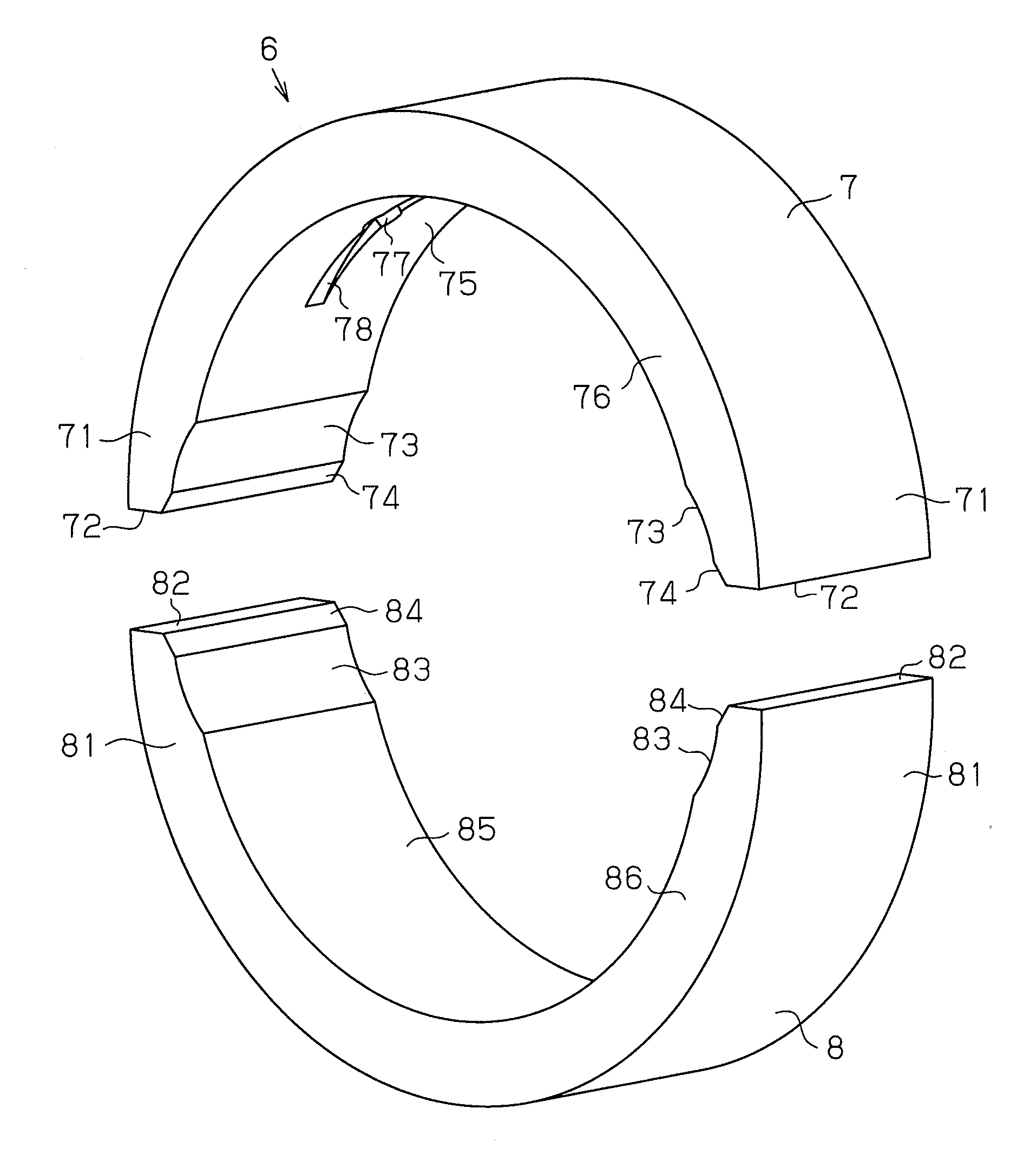
[0113](1) Each crank bearing 6 is provided with the non-undercut portion 7ER located on the side in the trailing direction AR of the inner circumference opening 77A of the oil hole 77. The oil groove 78 is formed to connect the inner circumference opening 77A of the oil hole 77 to the leading side matching surface 72F via the leading side crush relief 73F and the leading side chamfer 74F. Thus, since the amount of the engine oil 41 that is supplied to the oil clearance 60 on the side in the trailing direction AR of the inner circumference opening 77A of the oil hole 77 via the oil groove 78 is reduced, the amount of the engine oil 41 that flows out of the oil clearance 60 is reduced as compared to the case where the non-undercut portion 7ER is not provided. Also, since the amount of the engine oil 41 supplied to the second relief oil passage 65B and the second chamfer oil passage 66B is reduced, the amount of the engine oil 41 that flows out of the oil clearance 60 is reduced. Since...

second embodiment

[0137]Next, the present invention will be described with reference to FIG. 31.

[0138]The crank bearing 6 of the present embodiment is configured by modifying part of the crank bearing 6 of the first embodiment as follows. In FIG. 31, the components that are the same as those of the first embodiment are given the same reference numerals as the first embodiment.

[0139]As shown in FIG. 31, in the crank bearing 6 of the second embodiment, the width of the oil groove 78 is set equal to the diameter of the oil hole 77 (the diameter of the inner circumference opening 77A). Also, the depth of the oil groove 78 is set to be the greatest at the circumferential center CB of the oil groove 78. Moreover, the depth of the oil groove 78 is set to be gradually reduced from the circumferential center CB toward the trailing end portion 78R, and is zero at the trailing end portion 78R. Furthermore, the depth of the oil groove 78 is set to be gradually reduced from the circumferential center CB toward th...

third embodiment

[0142]Next, the present invention will be described with reference to FIG. 32.

[0143]The crank bearing 6 of the present embodiment is configured by modifying part of the crank bearing 6 of the first embodiment as follows. In FIG. 32, the components that are the same as those of the first embodiment are given the same reference numerals as the first embodiment.

[0144]As shown in FIG. 32, in the crank bearing 6 of the present embodiment, an oil hole 91 is provided at part of the middle bearing section 7E on the side in the leading direction AF of the oil hole 77. The oil hole 91 permits the engine oil 41 in the bearing oil groove 32R of the partition wall 32 to flow to the oil clearance 60 independently from the oil hole 77. The oil hole 91 is provided on the side in the leading direction AF of the circumferential center CA of the upper bearing 7. The diameter of the oil hole 91 is set equal to the diameter of the oil hole 77.

[0145]As described above, according to the crank bearing 6 of...


PUM


Abstract

A crank bearing is disclosed that includes a semicircular upper bearing and a semicircular lower bearing, which can be split from each other. The upper bearing includes a first oil passage for introducing engine oil from the outside to a gap between the crank bearing and a crank journal, and a second oil passage for permitting the engine oil to flow in the circumferential direction of the crank bearing. The first oil passage includes an inner circumference opening, which is open to the inner circumference of the main bearing. The upper bearing includes a non-undercut portion in which no oil passage is formed on the trailing side of the inner circumference opening in the rotational direction of the crank journal. A chamfer oil passage for discharging the engine oil in the second oil passage to the outside from the axial direction of the crank bearing is provided in at least one of the lower bearing and a region on the proceeding side of the circumference opening in the rotational direction of the crank journal.

Description

TECHNICAL FIELD[0001]The present invention relates to a slide bearing that is split into a pair of semicircular bearing bodies and supports a rotary shaft with lubricant.BACKGROUND ART[0002]The slide bearing is utilized as, for example, a crank bearing for supporting a crankshaft of an engine. A typical crank bearing is configured by a combination of a semicircular upper bearing and a semicircular lower bearing. The upper bearing is provided with an oil hole for supplying engine oil in the engine main body to an oil clearance, which is a space between the crank bearing and a crank journal, and an oil groove for permitting the engine oil supplied to the oil clearance through the oil hole to flow in the circumferential direction of the crank bearing.[0003]However, in the conventional crank bearing, since the oil groove is formed to connect one of matching surfaces of the upper bearing to the other matching surface, the lubricity of the crank bearing is reduced as the amount of the eng...

Claims


Application Information

Patent Timeline
IPC IPC(8): F16C33/10F02B77/00
CPCF01M2001/062F01M2011/026F16C3/14F16C33/106F16C9/04F16C17/02F16C33/046F16C9/02F16C17/022F16C2240/42F16C2360/22F16C33/10
Inventor MATSUYAMA, YUTAKA
Owner TOYOTA JIDOSHA KK
Why Eureka
Try Eureka