Syringe assembly, cap, and puncture needle

a technology of syringe and puncture needle, which is applied in the direction of intravenous devices, infusion needles, syringes, etc., can solve the problems of increased piercing resistance of patients upon use, increased pain of patients, etc., and achieves small piercing resistance, small piercing resistance, and reduced lubricant.

Active Publication Date: 2017-07-13
TERUMO KK
View PDF1 Cites 0 Cited by
  • Summary
  • Abstract
  • Description
  • Claims
  • Application Information

AI Technical Summary

Benefits of technology

[0013]According to the puncture needled configured in the above-described manner, the first lubricant-covered region has a smaller lubricant-covering thickness than the second lubricant-covered region, so that the amount of the lubricant can be reduced as compared with a case in which the lubricant is uniformly applied along the axial direction of the puncture needle. Further, though the first lubricant-covered region has a smaller lubricant-covering thickness than the second lubricant-covered region, the length of the first lubricant-covered region is suitably restricted, so that a sufficiently small piercing resistance can be obtained.
[0014]According to the syringe assembly, the cap, and the puncture needle of certain embodiments of the present invention, a sufficiently small piercing resistance and a full sealing property are compatible with each other.

Problems solved by technology

In this case, a whole or a part of the lubricant applied to the outer surface of the puncture needle may be wiped off, and eventually, the piercing resistance to the patient upon use may increase, and the patient will suffer from increased pain.

Method used


Image

  • Syringe assembly, cap, and puncture needle
  • Syringe assembly, cap, and puncture needle
  • Syringe assembly, cap, and puncture needle

Examples


Embodiment Construction

[0020]Hereafter, a syringe assembly, a cap, and a puncture needle according to the present invention will be described by way of example embodiments, with reference to the attached drawings.

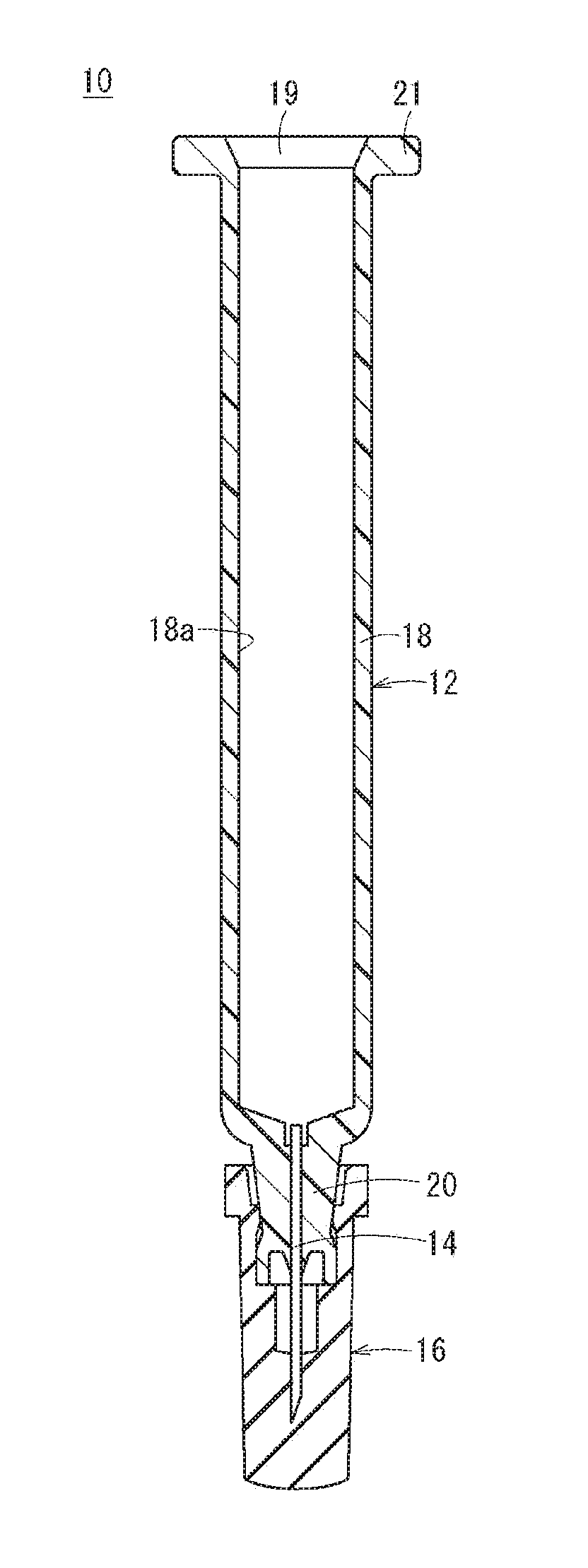
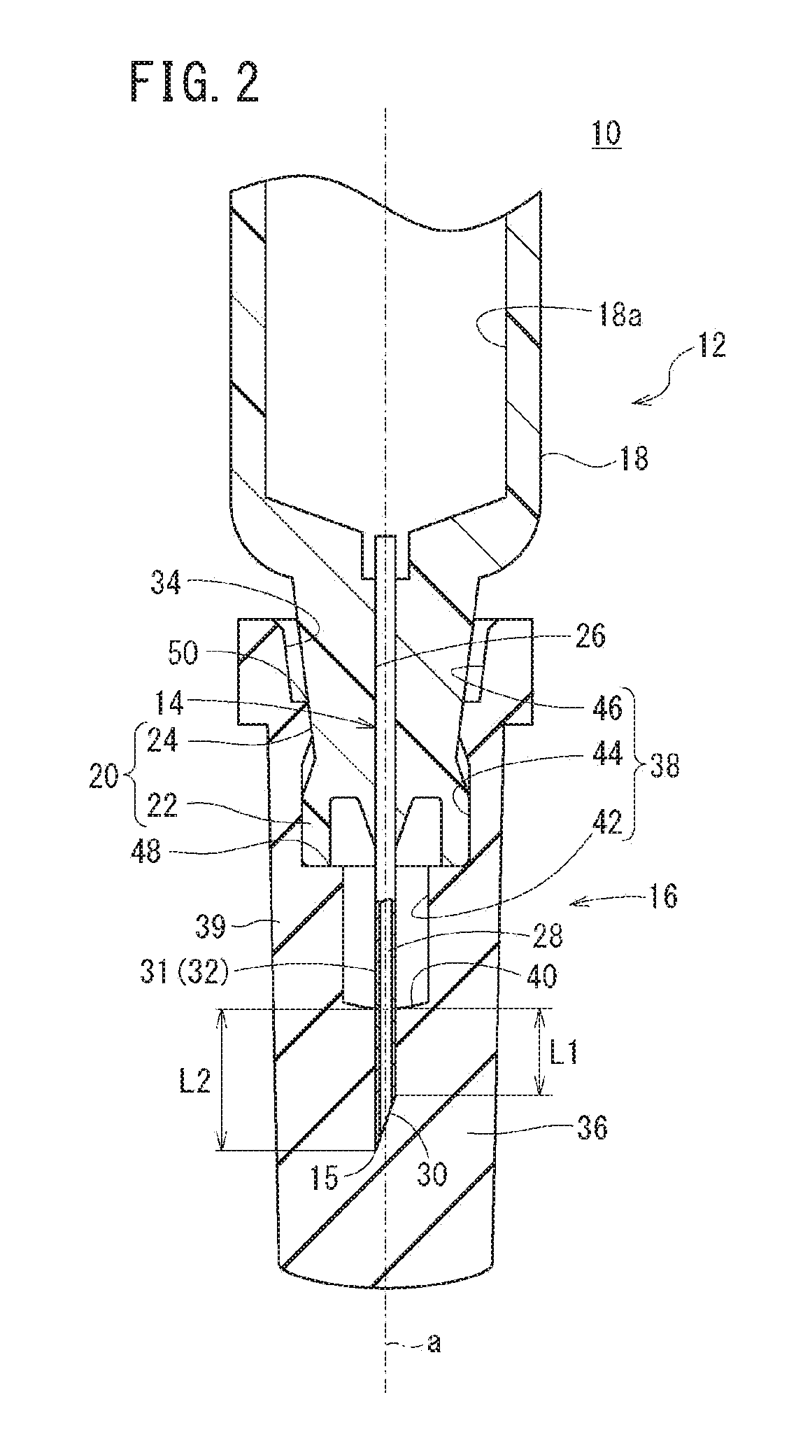
[0021]FIG. 1 is a schematic sectional view of a syringe assembly 10 according to one embodiment of the present invention. The syringe assembly 10 is provided with a barrel 12 having an interior space 18 a formed therein, a puncture needle 14 held by a distal end portion of the barrel 12, and a cap 16 mounted to the distal end portion of the barrel 12.

[0022]The syringe assembly 10 according to the present embodiment is configured as a prefilled syringe. That is, the interior of the barrel 12 of the syringe assembly 10 (interior space 18 a) is filled with a drug, and further a gasket is inserted at a given position, so as to configure the prefilled syringe. Also, a plunger may be mounted on a proximal end side of the gasket, or the gasket may have a shape such that a plunger can be mounted, in acco...


PUM


Abstract

A syringe assembly includes a barrel having a barrel tip portion, a puncture needle projecting from the barrel tip portion, and a cap that is detachably mountable to the barrel so as to seal a distal end of a needle hole. The cap has a receiving hole that receives the puncture needle, a bottom wall portion into which the puncture needle is inserted, and a stopper portion that defines an insertion length of the puncture needle relative to the bottom wall portion. In a state in which the cap is mounted to the barrel, the length from the most proximal position of a contact region between the cap and the puncture needle to the most proximal position of an edge surface is 1 to 3 mm.

Description

CROSS-REFERENCE TO RELATED APPLICATIONS[0001]The present application is a bypass continuation of PCT / JP 2015 / 069602, filed on Jul. 8, 2015, which claims priority to Japanese Application No. 2014-203388, filed on Oct. 1, 2014. These applications are hereby incorporated by reference in their entireties.BACKGROUND[0002]The present disclosure relates to a syringe assembly, a cap, and a puncture needle.[0003]For example, in a prefilled syringe that is filled with a drug liquid or the like in advance, a cap is detachably mounted to a tip portion of a barrel provided with a puncture needle, so as to protect the puncture needle and to seal a needle hole of the puncture needle, to prevent leakage of the drug liquid or the like. Further, it is known in the art to coat an outer surface of a puncture needle with a lubricant such as a silicone oil for the purpose of, for example, lowering the piercing resistance in injecting the drug liquid or the like into a human being or the like and alleviat...

Claims


Application Information

Patent Timeline
Patent Type & Authority Applications(United States)
IPC IPC(8): A61M5/32A61M5/28
CPCA61M5/3202A61M2005/311A61M2005/3107A61M5/285A61M5/343A61M2005/3109A61M5/28A61M5/32
Inventor FUNATSU, KAORIABE, YOSHIHIKOIIBUCHI, RURIKO
Owner TERUMO KK
Why Eureka
Try Eureka