Transceiver with Compensation for Transmit Signal Leakage and Method Therefor

a technology of transmit signal and compensation, applied in the field of transmission devices, can solve the problems of low degree of cross modulation, inability to successfully process the input circuit of the receiver's receive signal, and insufficient isolation of separate transmit and receive bands

Inactive Publication Date: 2010-02-25
CRESTCOM INC
View PDF14 Cites 85 Cited by
  • Summary
  • Abstract
  • Description
  • Claims
  • Application Information

AI Technical Summary

Benefits of technology

[0016]It is an advantage of at least one embodiment of the present invention that an improved transceiver with compensation for transmit signal leakage into a receive signal and method therefor are provided.

Problems solved by technology

But the use of separate transmit and receive bands seldom provides sufficient isolation when the transmitter and receiver share an antenna or use antennas located near one another.
When the power limits are exceeded, regardless of the frequency, the input circuits in the receiver cannot successfully process the receive signal.
In addition, when narrowband interfering signals are near the receive band, any nonlinear processing in the receiver's input circuits, such as amplifiers and / or mixers, causes some degree of cross modulation, which produces intermodulation products in the receive band.
Another way that the transmit signal may overwhelm the receiver results because the transmit signal itself often includes a small amount of energy in the receive band.
This receive-band energy portion of the transmit signal often results from intermodulation due to nonlinear processing in a high-power amplifier (HPA) at the output section of the transmitter and may also result from linear amplification of out-of-band thermal noise at the HPA input.
All other design parameters remaining equal, increased insertion loss directly causes a reduced link margin, leading to a reduced radio range, reduced data communication rates, increased error rates, and / or the like.
Any rippling or other inconstancy in this response produces distortion, which again leads to reduced radio range, reduced data communication rates, increased error rates, and / or the like.
An inadequately narrow transition band has conventionally lead to inadequate isolation and interference with the receive signal.
Unfortunately, improvements in one of these three design criteria (i.e., insertion loss, flat response, and narrow transition band) are usually achieved at the expense of at least one of the other two.
Thus, a good duplexer having truly desirable design characteristics is difficult to obtain.
Furthermore, the problems of obtaining a good duplexer are exacerbated as transmitter power increases.
As power increases, the ratio of the power of the transmit signal to the receive signal increases, making adequate isolation more difficult to achieve.
And, while printed and photolithographic devices, such as surface acoustic wave (SAW) devices and film bulk acoustic resonator (FBAR) devices, may provide good low cost, low power duplexers, such devices are not currently available for transceiver applications with transmit power greater than several watts.
For higher power applications, such as cellular base stations, which may transmit at up to several hundred watts of power, conventional duplexers that adequately balance insertion loss, flat response, and narrow transition band design criteria tend to be complex metallic structures that are complicated to manufacture, and often require individual manual tuning.
As a consequence, such duplexers tend to be one of the more expensive components of a transceiver.
Accordingly, multichannel TDD communication systems suffer the same isolation problems that FDD communication systems suffer, but they begin to suffer these problems at lower transmission power levels.
And, at higher power levels multichannel TDD communication systems have been deemed impractical due to such problems.
Prior art transceivers have attempted to implement the cancellation of a transmit signal from a receive signal, but such attempts have been met with limited success.
But the version of the transmit signal that interferes with the receive signal is influenced by duplexer distortions.
Since such duplexer distortions are not accounted for in the reference signal, the resulting cancellation is less effective than it might be.
Unfortunately, prior art transceivers have attempted to control the processing of reference signals used in cancellation exclusively using analog components.
As a result, reference signals are processed inaccurately, limited amounts of cancellation are achieved, and the character of cancellation is unsuitable for wideband transmit and / or receive signals.

Method used


Image

  • Transceiver with Compensation for Transmit Signal Leakage and Method Therefor
  • Transceiver with Compensation for Transmit Signal Leakage and Method Therefor
  • Transceiver with Compensation for Transmit Signal Leakage and Method Therefor

Examples


Embodiment Construction

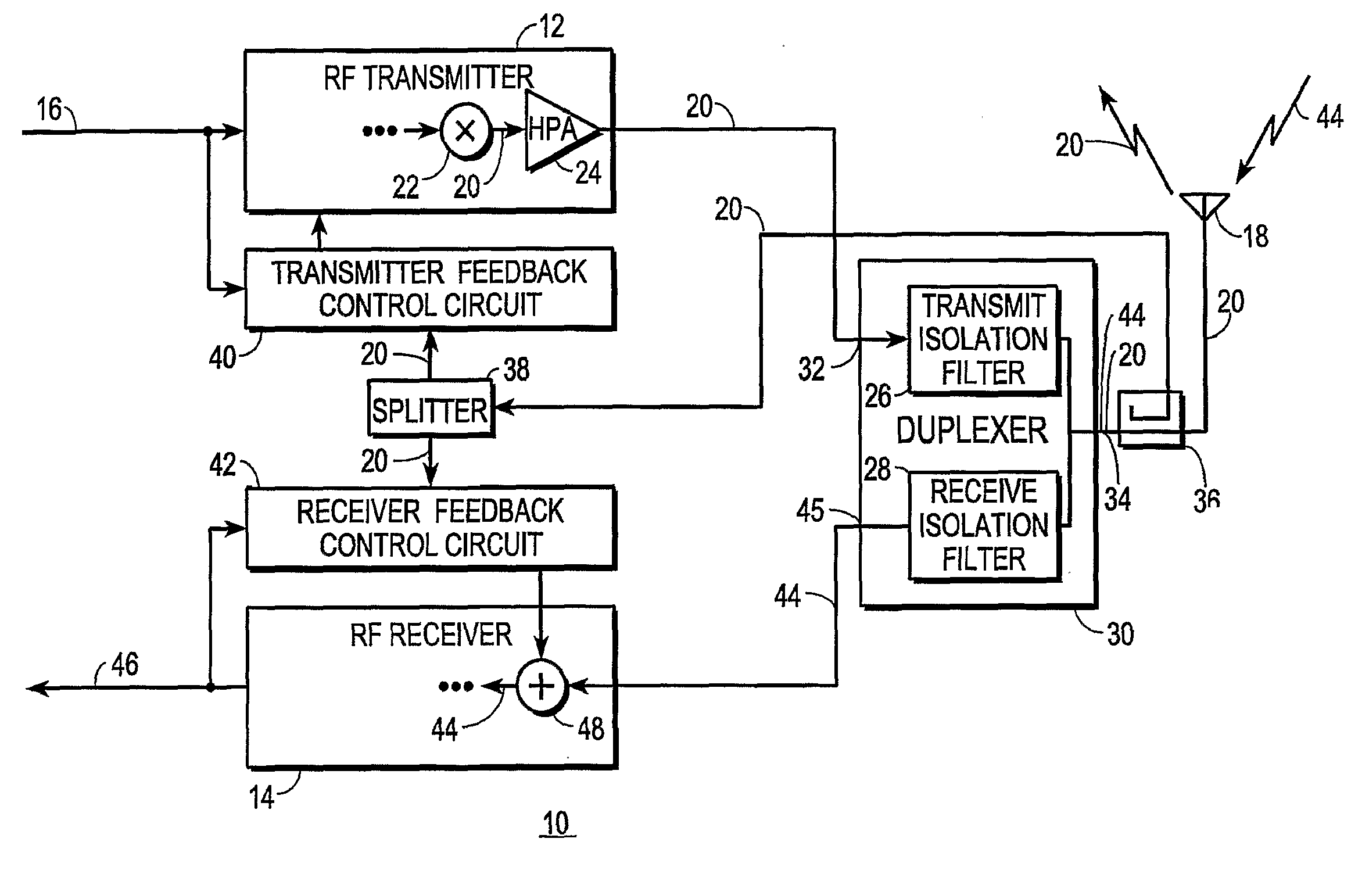
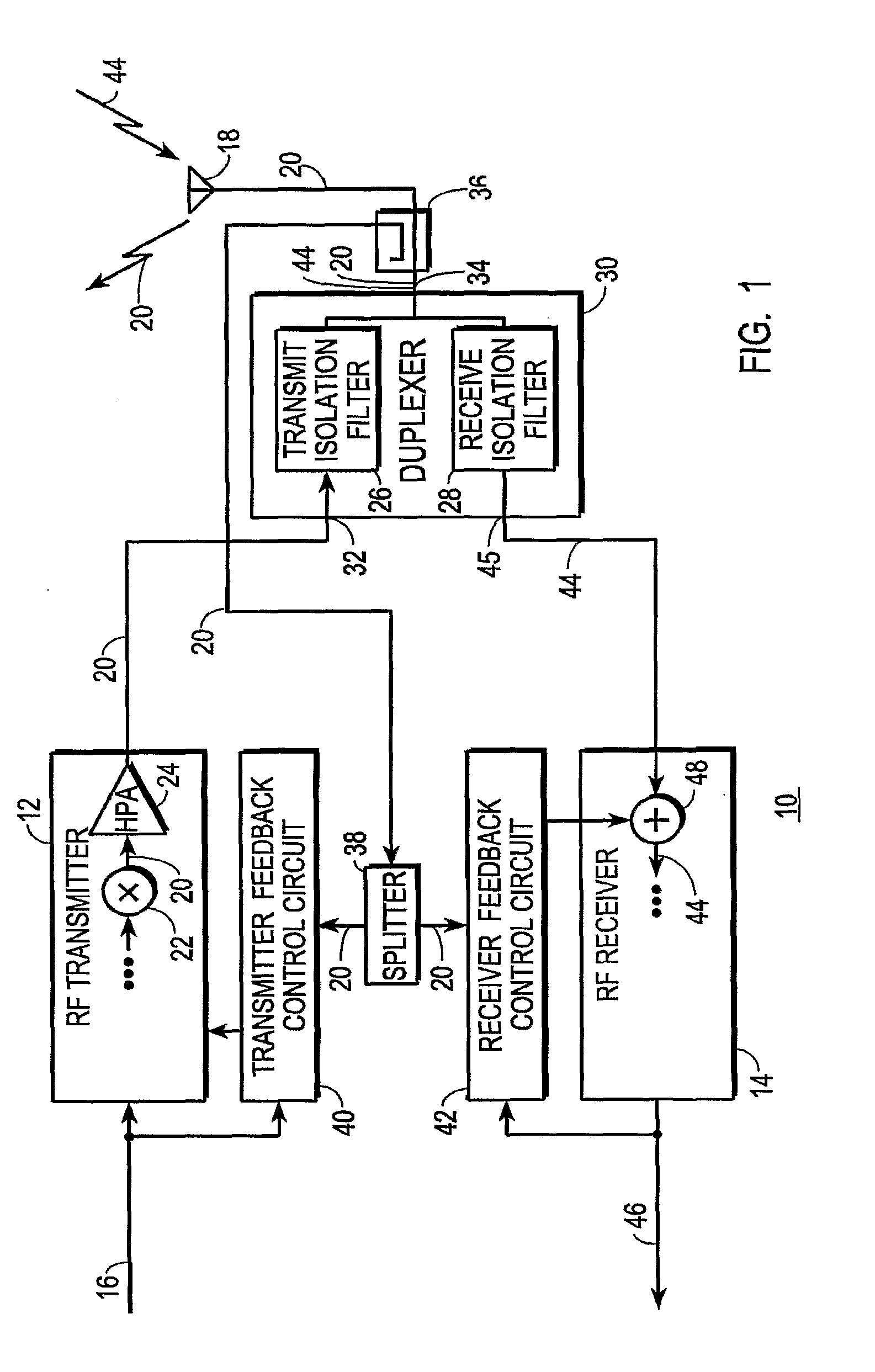
[0035]FIG. 1 shows a block diagram of a radio-frequency (RF) transceiver 10 configured in accordance with the teaching of the present invention. Transceiver 10 includes an RF transmitter 12 and an RF receiver 14. Transceiver 10 is the type of transceiver that may be used at a cellular telephony cell-site base station, but transceiver 10 may be used in other applications as well, including mobile subscriber equipment (e.g., cell phones, laptops, etc.).

[0036]A digitally modulated forward data stream 16 is provided to an input of RF transmitter 12. In a preferred embodiment, forward data stream 16 is a forward communication signal that conveys information and is arranged as a complex data stream having quadrature phase components. Those skilled in the art will appreciate that the complex notation is omitted herein from the figures in order to simplify the presentation of this subject matter. Forward data stream 16 propagates in a forward direction with respect to transmitter 12. In oth...


PUM


Abstract

A transceiver (10) includes an RF transmitter (12) and an RF receiver (14) coupled together through a duplexer (30) or non-filtering multiport device (30′). Either device may leak significant portions (56, 58) of the transmit signal (20) into the receive signal (44), and may significantly distort the transmit signal (20). Distortion is compensated in the transmitter (12) through the use of a linear predistorter (68) that is adjusted in response to an RF feedback signal obtained from the antenna-side of the device. Transmit signal leakage is compensated in the receiver (14) by producing an RF cancellation signal (106) that, when combined with the receive signal (44) at RF at least partially cancels the transmit signal portions (56, 58) leaked into the receive signal (44). Residual leakage signal and intermodulation products thereof may be cancelled digitally.

Description

TECHNICAL FIELD[0001]The present invention relates generally to the field of electronic communications. More specifically, the present invention relates to the field of transceivers, in which a transmitter and a receiver are physically located near one another, and in which the receiver benefits from being isolated from the transmitter.BACKGROUND ART[0002]When a transmitter and receiver are physically located near one another, the receiver needs to be isolated from the transmitter, particularly when the transmitter and receiver operate simultaneously. Isolation is needed so that the transmitter's transmitted signal does not interfere with the signal the receiver is trying to receive. The isolation may be aided to a great degree by configuring the transmitter and receiver to transmit and receive carrier signals respectively oscillating in non-overlapping frequency bands. But the use of separate transmit and receive bands seldom provides sufficient isolation when the transmitter and r...

Claims


Application Information

Patent Timeline
Patent Type & Authority Applications(United States)
IPC IPC(8): H04B1/44
CPCH04B2001/0416H04B1/525
Inventor MCCALLISTER, RONALD DUANE
Owner CRESTCOM INC
Why Eureka
Try Eureka