Sample preparation apparatus

a technology of sample preparation and sample, which is applied in the direction of level control, burettes/pipettes, packaging goods types, etc., can solve the problems of time-consuming process, impractical real-time threat assessment, and high cost and often inefficien

Inactive Publication Date: 2010-03-04
MICROFLUIDIC SYST
View PDF76 Cites 54 Cited by
  • Summary
  • Abstract
  • Description
  • Claims
  • Application Information

AI Technical Summary

Benefits of technology

[0009]In one aspect, an apparatus to process an input fluid sample including one or more targeted analytes is disclosed. The apparatus includes a master fluid driver, a plurality of individually actuated fluid valves, a plurality of slave fluid drivers, and fluid lines coupled to the master fluid driver, the plurality of fluid valves, and the plurality of slave fluid drivers. The master fluid driver is configured to be actuated in discrete increments. The plurality of individually actuated fluid valves are configured to regulate fluid flow, wherein each fluid valve is configured to be actuated no more than once. The plurality of slave fluid drivers are coupled to the master fluid driver, wherein actuation of the master fluid driver selectively actuates the plurality of slave fluid drivers according to a number of increments the master slave fluid driver is incremented and according to a number of fluid valves that are actuated. The apparatus is fully loaded with a plurality of processing fluids and the fluid sample, further wherein the selective actuation of the plurality of slave fluid drivers functions to selectively displace the one or more targeted analytes between a plurality of processing areas and to selectively provide one or more of the plurality of processing fluids to the processing areas.
[0010]In another aspect, another apparatus to process an input fluid sample including one or more ta

Problems solved by technology

However, the specific type of particle is not identified by such a collection and detection apparatus.
This is a time-consuming process requiring various pieces of test equipment, which is impractical for real-time threat assessment.
Such processes also require the interaction of a human operator, which is costly and often inefficient.
For large volume fluid samples, such as 1 ml or greater, extraction of the potential pathogens is p

Method used


Image

  • Sample preparation apparatus
  • Sample preparation apparatus
  • Sample preparation apparatus

Examples


third embodiment

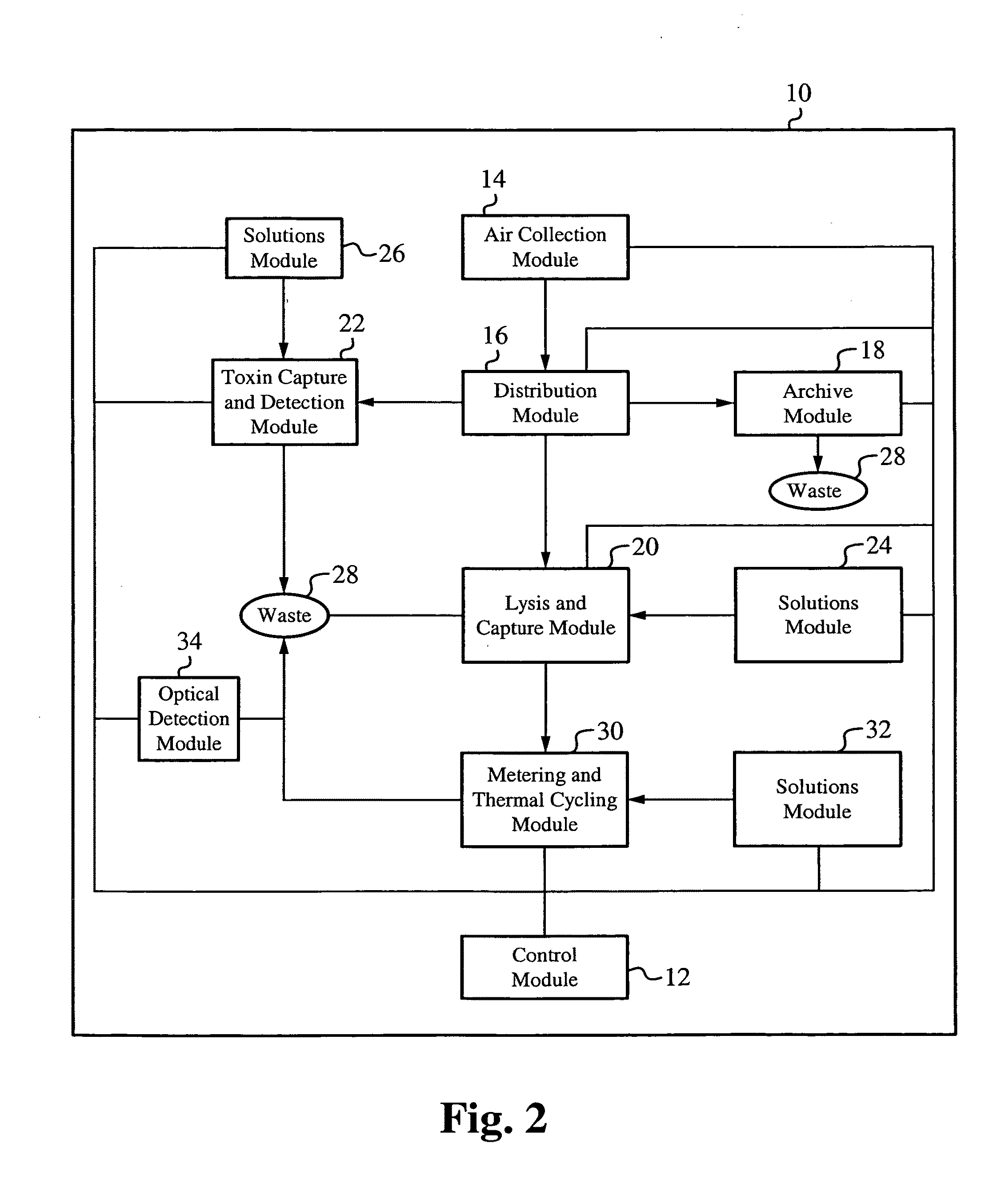
[0095]FIG. 12 illustrates an exemplary functional block diagram of the integrated collection and detection system. The integrated collection and detection system 600 includes the air collection module 510 and the confirmation device 520 of the collection and detection system 500, and the distribution module 16, the archive module 18, the lysis and capture module 20, the toxin capture and detection module 22, the solutions module 24, the solutions module 26, the waste module 28, the metering and thermal cycling module 30, the solutions module 32, and the optical detection module 34 of the collection and detection system 10. The collection and detection system 600 also includes a distribution module 610 and a control module 620. Each of the modules are fluidically coupled as appropriate to direct fluid sample and solutions within the collection and detection system 600.

[0096]Control of the collection and detection system 600 is maintained by the control module 620, which includes the ...

first embodiment

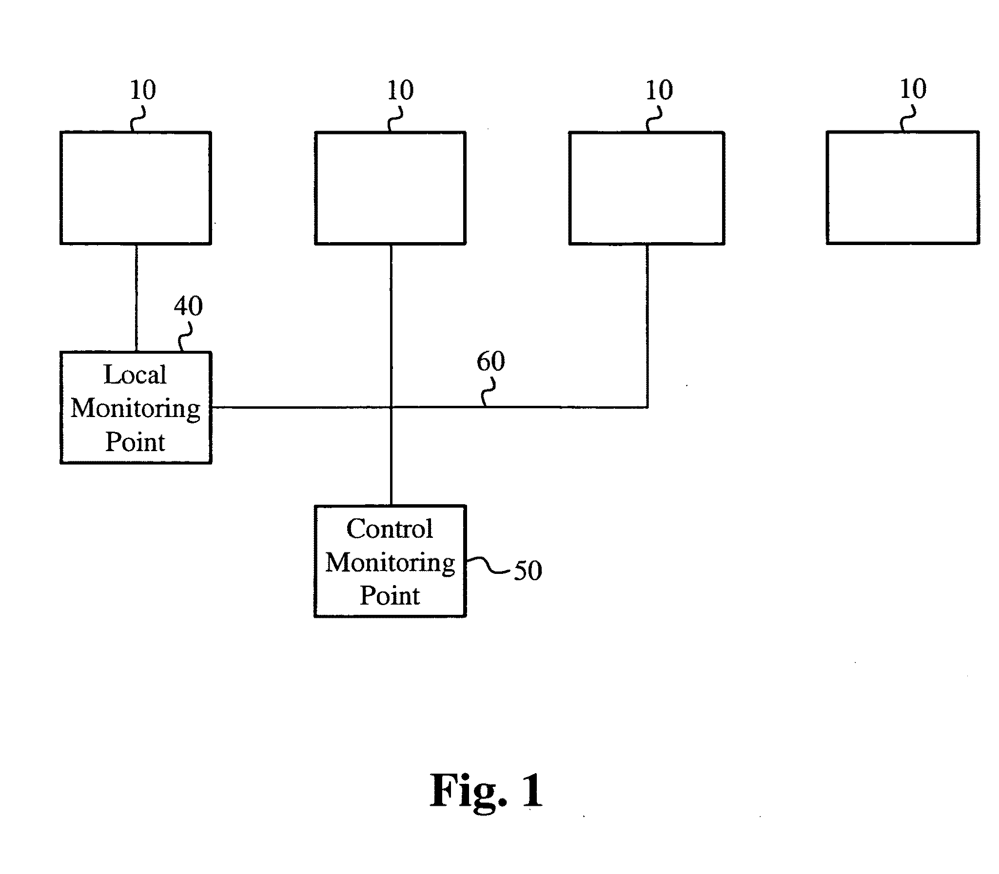
[0106]The network configuration described in relation to FIG. 1 includes the collection and detection system, the collection and detection system 10. It is understood that one, some, or all of the embodiments of the collection and detection system, for example the collection and detection system 10, the detection and collection system 500, and the collection and detection system 600, can be networked in a similar manner and in any combination.

[0107]The embodiments of the collection and detection system described above are for exemplary purposes. The microfluidic circuitry and module nature of the integrated collection and detection system provides flexibility and extensibility to interconnect and configure the modules, and associated sub-modular components, into any desired combination. Additionally, the specific configurations described for each of the modules is for exemplary purposes. The microfluidic circuitry and constituent components of each module can be adapted into any num...

second embodiment

[0126]FIG. 15 illustrates an exemplary schematic block diagram of a capture and purification apparatus configured according to a A capture and purification apparatus 900 is configured similarly as the capture and purification apparatus 800 (FIG. 14) except that the fluid reservoir 850 (FIG. 14) is removed so that the fluid solution previously output from the valve 840 to the fluid reservoir 850 is instead provided directly to the SEC column 880 via microfluidic circuitry. Also, the capture and purification apparatus 900 includes a sensor 894. In the exemplary application where the buffer solution used to elute the targeted analytes captured in the ion-exchange chromatography column 830 is a high salt concentration buffer solution, the sensor 894 is a salt detector.

[0127]Operation of the capture and purification apparatus 900 is now described in terms of the exemplary application where the targeted analytes are nucleic acids and the wash steps are performed using various concentrati...


PUM

PropertyMeasurementUnit
Forceaaaaaaaaaa

Abstract

A capture and purification apparatus is configured as a stand-alone apparatus or as part of a larger system. The capture and purification apparatus can be configured as a microfluidic cartridge that includes microfluidic circuitry and individually controlled valves. The microfluidic cartridge can be configured to function independently, or can be configured to be coupled to a separate instrument that provides the actuation to perform the capture and purification process. The capture and purification apparatus is configured as a volume-driven system that applies single-direction valves, a single fluid driving device, and fluid lines to control and discretely direct fluid flow within a full-loaded fluidic system. Such control enables various fluid sample processing techniques to be performed including, but not limited to, lysis, thermal cycling, and/or target analyte capture and purification, for example using a combination of ion-exchange chromatography and size-exclusion chromatography (SEC).

Description

RELATED APPLICATIONS[0001]This patent application is a continuation-in-part of U.S. patent application Ser. No. 12 / 231,171, filed on Aug. 28, 2008, and entitled “Method and Apparatus for Purifying and Collecting Analytes.” This application incorporates U.S. patent application Ser. No. 12 / 231,171, filed on Aug. 28, 2008, entitled “Method and Apparatus for Purifying and Collecting Analytes”, in its entirety by reference.GOVERNMENT LICENSE RIGHTS[0002]This invention was made with Government support under Agreement No. W81XWH-04-9-0010 awarded by the Government. The Government has certain rights in this invention.FIELD OF THE INVENTION[0003]The invention relates to a method of and apparatus for preparing one or more target analytes for analysis. More particularly, the invention relates to preparing one or more target analytes including capturing and purifying one or more target analytes from a sample.BACKGROUND OF THE INVENTION[0004]Bio-threat detectors are used to monitor the ambient a...

Claims


Application Information

Patent Timeline
IPC IPC(8): G01N30/84C12M1/00
CPCB01L3/502715Y10T436/2575B01L3/502738B01L7/52B01L2200/04B01L2200/0621B01L2200/10B01L2200/16B01L2300/0681B01L2300/0816B01L2300/0867B01L2300/1827B01L2400/0478B01L2400/0622G01N30/96G01N35/08B01L3/50273
Inventor YUAN, BOB
Owner MICROFLUIDIC SYST
Why Eureka
Try Eureka