Power output apparatus, vehicle equipped with power output apparatus, and control method of power output apparatus

a technology of power output apparatus and power output device, which is applied in the direction of electric propulsion mounting, machine/engine, electric propulsion mounting, etc., can solve the problem of difficult continuous output of relatively large torque, and achieve the effect of preventing excessive heat evolution, adequate control, and large torqu

Inactive Publication Date: 2010-03-04
TOYOTA JIDOSHA KK
View PDF21 Cites 57 Cited by
  • Summary
  • Abstract
  • Description
  • Claims
  • Application Information

AI Technical Summary

Benefits of technology

[0009]In the power output apparatus according to this aspect of the invention, in the state of connection of both the first motor and the second motor with the driveshaft by means of the speed change-transmission assembly to output power to the driveshaft, the first motor and the second motor are controlled to substantially equalize the output torque of the first motor with the output torque of the second motor and to ensure output of a power, which is equivalent to a power demand as a power required for the driveshaft, to the driveshaft. In the state of connection of both the two motors with the driveshaft by means of the speed change-transmission assembly, the power output apparatus of this arrangement ensures continuous output of a relatively large torque with prevention of excessive heat evolution from either one of the first motor and the second motor, while adequately controlling the two motors by a relatively simple control procedure.
[0010]In one preferable embodiment of the invention, the power output apparatus of the above aspect further has: an internal combustion engine; a power distribution integration mechanism configured to have a first element connecting with the rotating shaft of the first motor, a second element connecting with the rotating shaft of the second motor, and a third element connecting with an engine shaft of the internal combustion engine and arranged to allow mutually differential rotations of the three elements; and a connecting-disconnecting device configured to attain driving source element connection and release of the driving source element connection. The driving source element connection may be any one of connection of the first motor with the first element, connection of the second motor with the second element, and connection of the internal combustion engine with the third element. The driving source element connection may be released by the connecting-disconnecting device and operation of the internal combustion engine may be stopped when both the first motor and the second motor are connected to the driveshaft by the speed change-transmission assembly. The power output apparatus of this embodiment adequately changes over the driving state between a drive mode with output of the power to the driveshaft accompanied by operation of the internal combustion engine and a drive mode with transmission of the power from at least one of the first motor and the second motor to the driveshaft by means of the speed change-transmission assembly. This arrangement desirably improves the energy efficiency and the power transmission efficiency of the power output apparatus.
[0012]The motor vehicle according to this aspect of the invention connects both the two motors to the driveshaft by means of the speed change-transmission assembly and thereby ensures continuous output of a relatively large torque. The motor vehicle of this arrangement accordingly has the improved hill climbing performance and the improved towing performance in a motor drive mode with these motors.
[0014]In the state of connection of both the first motor and the second motor with the driveshaft by means of the speed change-transmission assembly to output the power to the driveshaft, the control method of this arrangement ensures continuous output of a relatively large torque with prevention of excessive heat evolution from either one of the first motor and the second motor, while adequately controlling the two motors by a relatively simple control procedure.

Problems solved by technology

It is, however, rather difficult to continuously output a relatively large torque with only one motor from the viewpoints of the energy efficiency and the potential heat generation in the motors.

Method used


Image

  • Power output apparatus, vehicle equipped with power output apparatus, and control method of power output apparatus
  • Power output apparatus, vehicle equipped with power output apparatus, and control method of power output apparatus
  • Power output apparatus, vehicle equipped with power output apparatus, and control method of power output apparatus

Examples


Embodiment Construction

[0031]One mode of carrying out the invention is described below as a preferred embodiment.

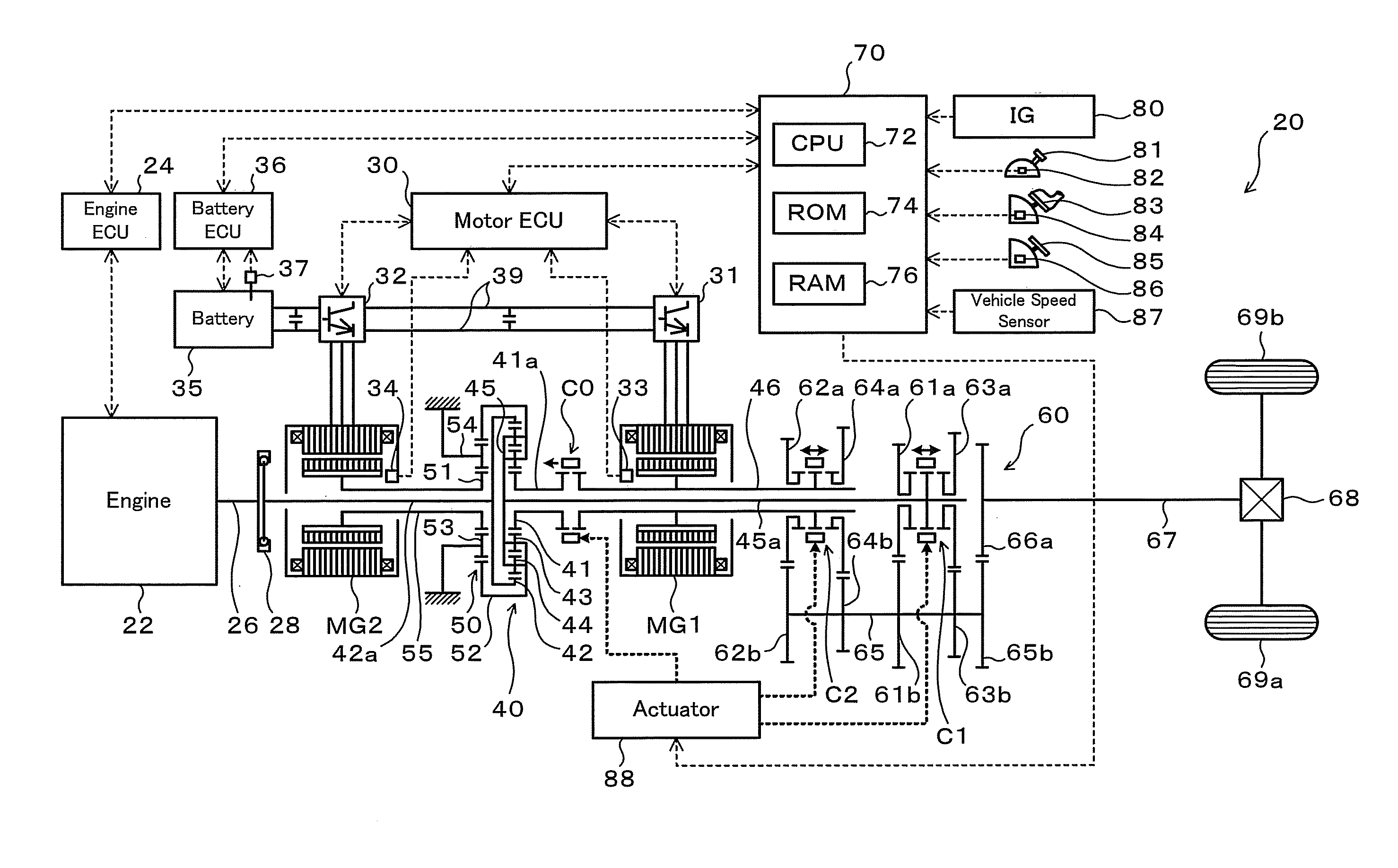
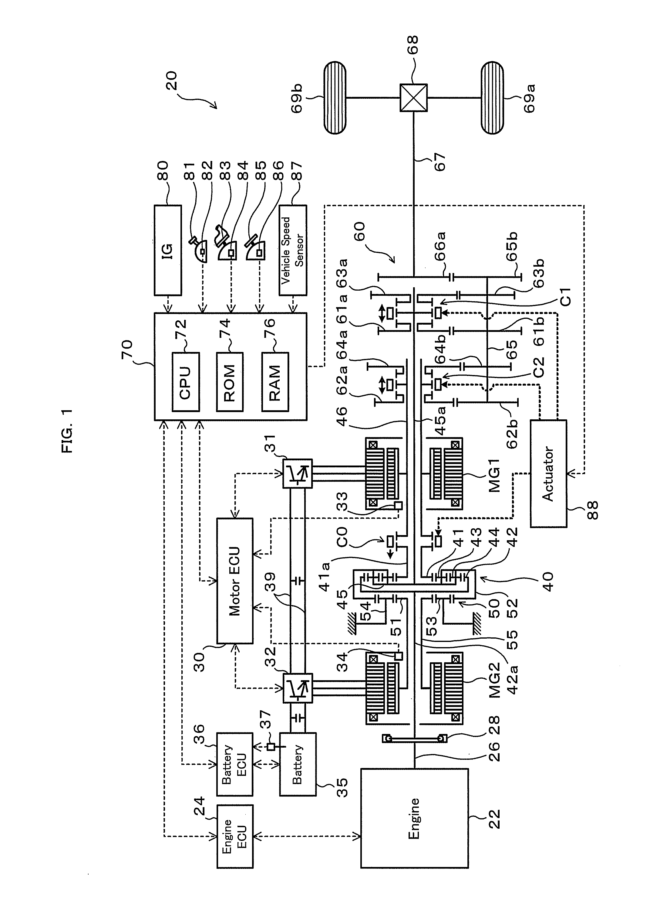
[0032]FIG. 1 schematically illustrates the configuration of a hybrid vehicle 20 in one embodiment of the invention. The hybrid vehicle 20 shown in FIG. 1 is constructed as a rear-wheel drive vehicle and includes an engine 22 located in a front portion of the vehicle, a power distribution integration mechanism (differential rotation mechanism) 40 connected with a crankshaft 26 or an output of the engine 22, a motor MG1 connected with the power distribution integration mechanism 40 and designed to have power generation capability, a motor MG2 arranged coaxially with the motor MG1 to be connected with the power distribution integration mechanism 40 via a reduction gear mechanism 50 and designed to have power generation capability, a transmission 60 constructed to transmit the output power of the power distribution integration mechanism 40 with a speed change to a driveshaft 67, and a hybrid electr...


PUM


Abstract

In a 2-motor drive mode with connection of both motors with a driveshaft by means of a transmission, a hybrid vehicle sets torque commands of the motors to substantially equalize an output torque of the second motor with an output torque of the first motor and to ensure output of a torque equivalent to a preset torque demand to the driveshaft. This arrangement ensures continuous output of a relatively large torque.

Description

TECHNICAL FIELD[0001]The present invention relates to a power output apparatus configured to output power to a driveshaft, a vehicle equipped with such a power output apparatus, and a control method of such a power output apparatus.BACKGROUND ART[0002]One proposed structure of the power output apparatus includes an internal combustion engine, two motors, a Ravigneaux planetary gear mechanism, and a parallel shaft-type transmission arranged to selectively connect two output elements of the planetary gear mechanism to an output shaft (see, for example, Patent Document 1). Another proposed structure of the power output apparatus has a planetary gear mechanism including an input element connected with an internal combustion engine and two output elements, and a parallel shaft-type transmission including a countershaft connected with the respective output elements of the planetary gear mechanism (see, for example, Patent Document 2).[0003]Patent Document 1: Japanese Patent Laid-Open No. ...

Claims


Application Information

Patent Timeline
Patent Type & Authority Applications(United States)
IPC IPC(8): B60K6/442B60W10/04B60W20/00B60K6/365B60K6/387B60K6/445B60K6/547B60L50/16B60W10/02B60W10/06B60W10/08B60W10/10F02D29/02
CPCB60K1/02Y10T477/23B60K6/387B60K6/445B60K6/547B60L11/14B60L15/10B60W10/02B60W10/06B60W10/08B60W10/113B60W10/115B60W20/00F16H3/006F16H2037/0873Y02T10/6239Y02T10/6286Y02T10/646Y02T10/7077Y02T10/648Y02T10/70B60L2200/26B60K6/365B60L50/16Y02T10/62Y02T10/64Y02T10/7072B60W2510/083B60W20/10B60W10/24B60W10/10B60W2710/083
Inventor KATSUTA, HIROSHIOBA, HIDEHIRO
Owner TOYOTA JIDOSHA KK
Why Eureka
Try Eureka