Method and Apparatus for the Measurement of Signals from Radiation Sensors

a radiation sensor and signal technology, applied in the direction of radiation intensity measurement, instruments, x/gamma/cosmic radiation measurement, etc., can solve the problems of poor mobility, large non-uniformity, and strong limited spectral resolution of these materials

Active Publication Date: 2010-03-04
BROOKHAVEN SCI ASSOCS +1
View PDF3 Cites 21 Cited by
  • Summary
  • Abstract
  • Description
  • Claims
  • Application Information

AI Technical Summary

Problems solved by technology

The spectral resolution of these materials is strongly limited by several deficiencies (e.g., the poor mobility of holes, electron trapping, and extensive non-uniformities).
Most high-Z semiconductor sensors, like those including cadmium zinc telluride (CdZnTe) or mercuric iodide (HgI2), have poor charge transport properties.
One drawback of this approach is the dependence of the timing measurement on the amplitude of the cathode signal.
Due to the number of measurements involved, the resulting timing t0 is affected by error in an amount that depends on the ionized charge and number of anodes involved.
Some drawbacks of this approach are moderate filtering with consequently poor signal-to-noise ratio, continuous switching or digital activity required by the multiple sampling before and during the waveform, and the requirement of multiple analog memories and associated analog-to-digital conversions that can limit in the rate capability of the detector.
In addition to the poor charge transport properties, high Z semiconductor radiation sensors are affected by charge trapping.
The charge trapping effects cause considerable degradation of the spectral response of these detectors because the amount of charge measured depends on the depth of the ionizing event.
For some anodes, the charge can be very small and the measurement can be strongly affected by noise.
As a result, the spectral performance for ionizing interactions that result in charge sharing or multiple interacting events can be considerably degraded.
The measurement of the cathode timing is typically more difficult than that of the anode timing because the ramp signal at the output of the charge amplifier for the cathode is very slow and initially very small in amplitude.

Method used


Image

  • Method and Apparatus for the Measurement of Signals from Radiation Sensors
  • Method and Apparatus for the Measurement of Signals from Radiation Sensors
  • Method and Apparatus for the Measurement of Signals from Radiation Sensors

Examples


Embodiment Construction

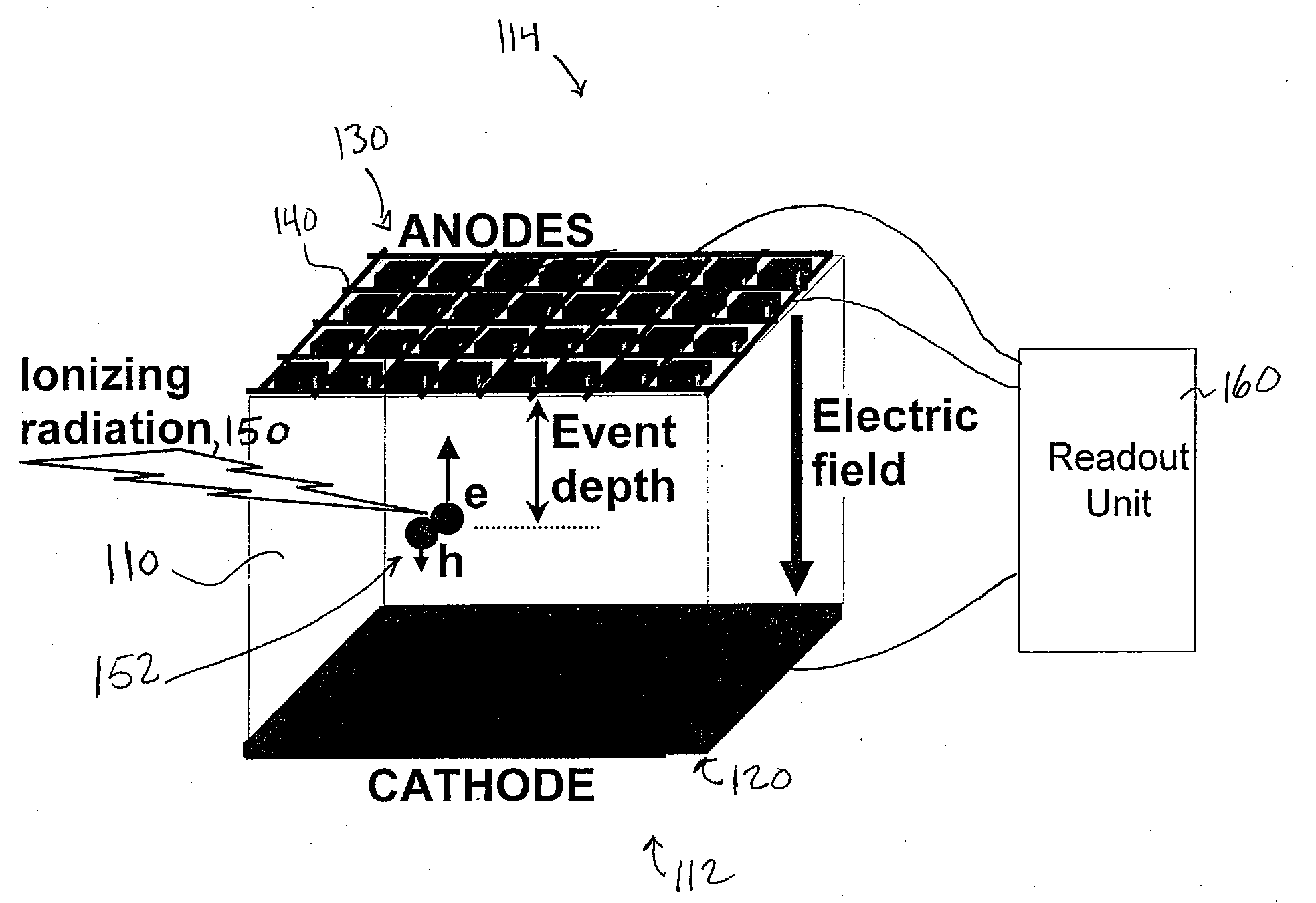
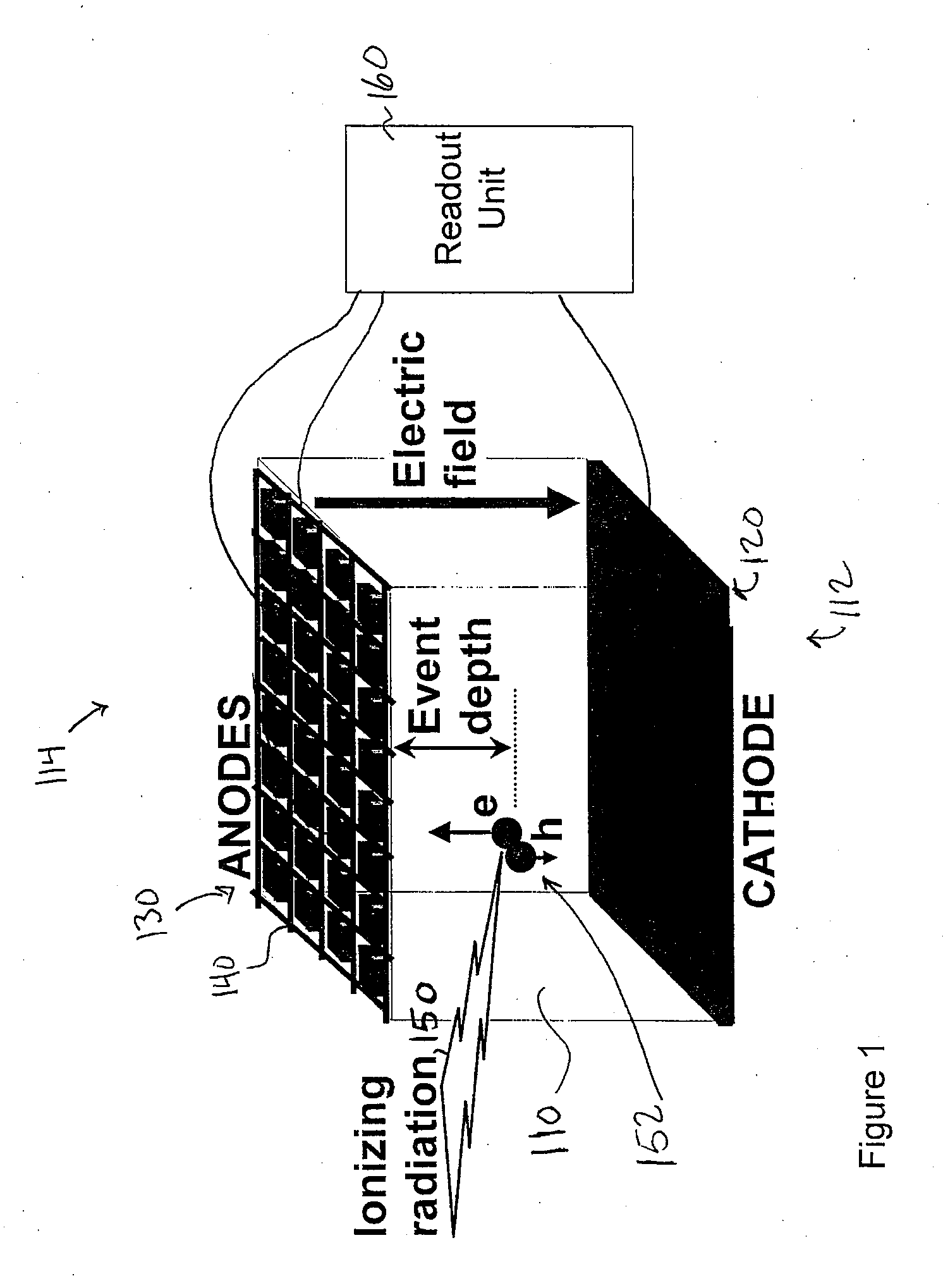
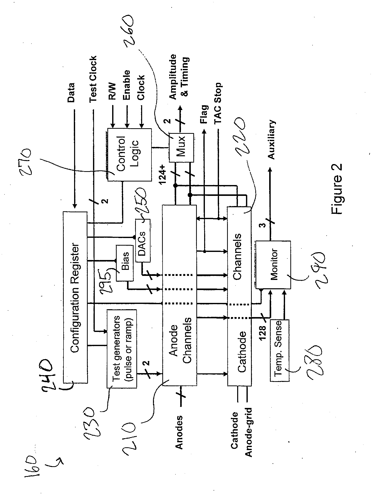
[0030]The preferred embodiments of the present invention include readout units for 3D position-sensitive radiation detectors having low-noise charge amplification, and filtering, and that can perform measurements of amplitude and timing on signals from a cathode, anodes, and / or anode grid. The readout units can be configured to read-out signals from pixilated CZT sensors, characterized by an array of anodes and at least one, cathode. In response to an ionizing event, the readout units measure a peak amplitude and relative timing from anodes and at least one cathode. The readout units can be implemented as application specific integrated circuits (ASICs) that can be wire-bonded to a 22×22 mm2 interposer, which can be connected to a sensor and which can be used for analog and digital power supplies and signals.

[0031]FIG. 1 depicts an exemplary position sensitive radiation detector 100 (detector 100). The detector 100 can include a detector medium 110, cathode 120, at least one anode, ...


PUM


Abstract

The preferred embodiments of the present invention include a device for measuring an ionizing event in a radiation sensor. The device can include a charge amplifier and a timing shaper. The charge amplifier receives a cathode signal and is configured to output an amplified cathode signal. The timing shaper is operatively connected to the charge amplifier to receive the amplified cathode signal. The timing shaper is configured to generate a first pulse in response to a beginning of the ionizing event and a second pulse in response to an end of the ionizing event. The first and second pulses are associated with a depth of interaction of the ionizing event and are generated in response to a slope of the amplified cathode signal changing.

Description

[0001]This invention was made with Government support under contract number DE-AC02-98CH10886, awarded by the U.S. Department of Energy. The Government has certain rights in the inventionBACKGROUND[0002]High-Z semiconductor radiation sensors typically include a cathode electrode and at least one anode electrode. The cathode and anode are typically disposed on opposite ends of a detector medium. The detector medium is conventionally composed of cadmium zinc telluride (CdZnTe or CZT), mercuric iodide (HgI2), or the like. An electrical potential is applied to the cathode and the anode to create an electrical field between the cathode and anode.[0003]Cadmium-Zinc-Telluride (CZT) sensors have emerged as leading candidates in room-temperature, large-volume, gamma-ray spectrometry for security, medical, industrial, and space applications. More recently another wide-bandgap material, mercuric iodide (HgI2), has been suggested as a potential candidate. The spectral resolution of these materi...

Claims


Application Information

Patent Timeline
Patent Type & Authority Applications(United States)
IPC IPC(8): G01T1/24
CPCG01T1/247
Inventor DE GERONIMO, GIANLUIGI
Owner BROOKHAVEN SCI ASSOCS
Why Eureka
Try Eureka