Permanent-Magnet (PM) Rotors and Systems

a permanent magnet, rotor technology, applied in the direction of magnetic circuit rotating parts, dynamo-electric machines, magnetic circuit shape/form/construction, etc., can solve the problems of affecting the performance of the servo system, unable to ensure that the current feeding a bdcm is square-wave current, and relatively inefficient traditional winding-based rotors, etc., to achieve the effect of improving performance, reducing flux leakage, and suitable magnetic insulation properties

Inactive Publication Date: 2010-03-04
TECO WESTINGHOUSE MOTOR
View PDF99 Cites 41 Cited by
  • Summary
  • Abstract
  • Description
  • Claims
  • Application Information

AI Technical Summary

Benefits of technology

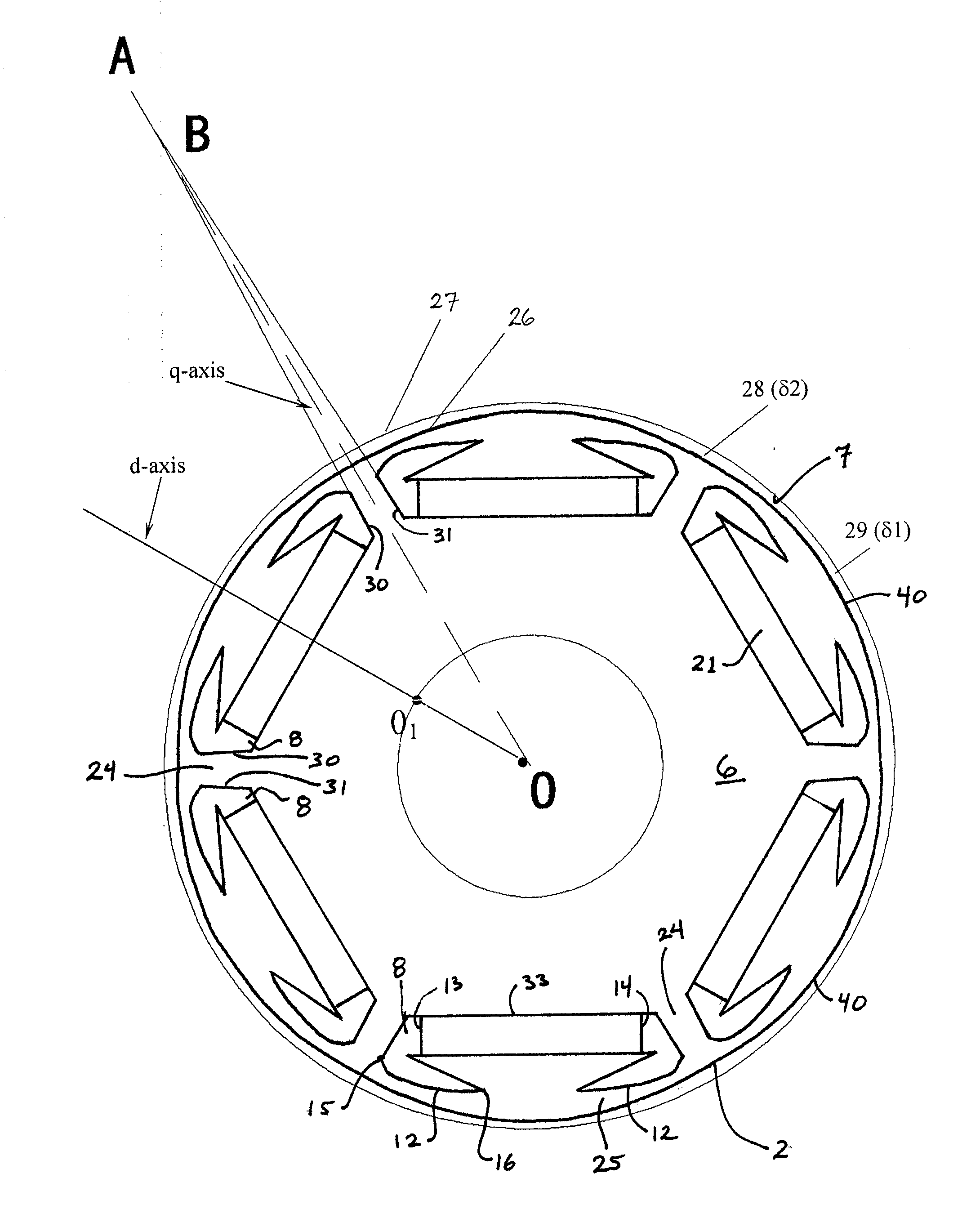
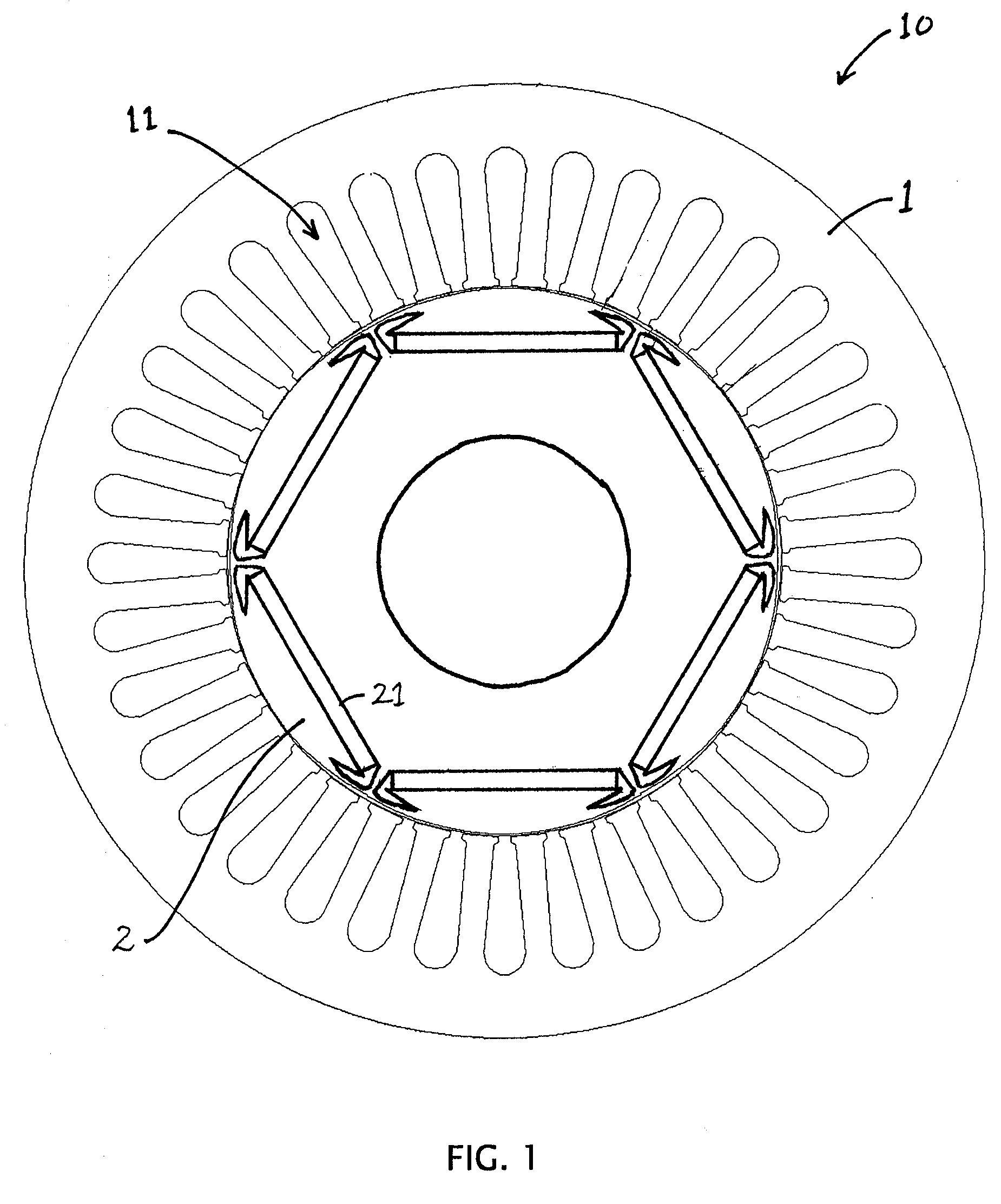
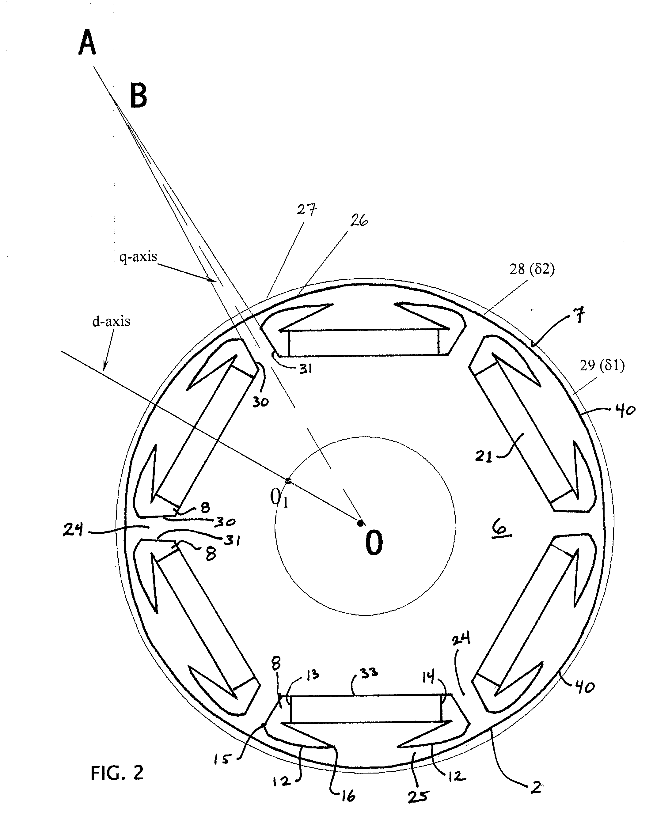
[0013]Embodiments of the present PM rotors include radial-magnet configurations, and/or rotors with magnetic insulation bridges configured to provide mechanical strength and suitable magnetic insulation properties, and/or magnetically insulating open spaces between the PM bulks and the magnetic insulation brides, and/or outer perimeters configured to provide a non-uniform air gap between the outer perimeter of the rotor and the inner perimeter of a stator within which the rotor can be used. Embodiments of the present rotors can be configured such that in operation, the air gap-flux density waveform is relatively more sinusoidal (e.g., compared to prior rotors), and/or such that harmonics are suppressed

Problems solved by technology

Such traditional winding-based rotors are relatively inefficient compared with PM rotors, and PM rotors may generally be made smaller than traditional winding-based rotors for a given capacity or output.
By means of current control, it is generally possible to ensure that the current feeding a PMSM is sinusoidal, but it is often impossible to ensure that the current feeding a BDCM is square-wave current.
But in low-speed operation, these torque ripples can negatively affect servo system performance.
The challenge for this rotor configuration is that the magnetic-insulation bridges between adjacent PM bulks must be large enough to avoid mechanical damage (e.g., resist mechanical stresses) during high-speed rotation of the rotor.
But if the magneti

Method used


Image

  • Permanent-Magnet (PM) Rotors and Systems
  • Permanent-Magnet (PM) Rotors and Systems
  • Permanent-Magnet (PM) Rotors and Systems

Examples


Embodiment Construction

[0033]The term “coupled” is defined as connected, although not necessarily directly, and not necessarily mechanically; two items that are “coupled” may be integral with each other. The terms “a” and “an” are defined as one or more unless this disclosure explicitly requires otherwise. The terms “substantially,”“approximately,” and “about” are defined as largely but not necessarily wholly what is specified, as understood by a person of ordinary skill in the art.

[0034]The terms “comprise” (and any form of comprise, such as “comprises” and “comprising”), “have” (and any form of have, such as “has” and “having”), “include” (and any form of include, such as “includes” and “including”) and “contain” (and any form of contain, such as “contains” and “containing”) are open-ended linking verbs. As a result, a device or system that that “comprises,”“has,”“includes” or “contains” one or more elements possesses those one or more elements, but is not limited to possessing only those elements. Like...


PUM


Abstract

Permanent-magnet (PM) rotors, rotor components, and machines using PM rotors, where the PM rotors have internally coupled PM bulks and/or are configured to have a non-uniform air gap between the rotor and a stator.

Description

RELATED APPLICATIONS[0001]This application claims benefit under 35 U.S.C. §119(a) to Chinese utility model registration No. 200820163707.4, filed on Aug. 28, 2008, which is incorporated by reference.BACKGROUND[0002]1. Field of the Invention[0003]The present invention relates generally to rotors and electrical machines using rotors, and, more particularly, but not by way of limitation, to permanent-magnet (PM) rotors, rotor components, and machines comprising PM rotors.[0004]2. Description of Related Art[0005]Rotors and machines using rotors have been known in the art for some time. For example, electrical machines such as motors traditionally include brushes and a rotor with wire windings. Such traditional winding-based rotors are relatively inefficient compared with PM rotors, and PM rotors may generally be made smaller than traditional winding-based rotors for a given capacity or output. As a result, machines using PM rotors may generally be made smaller than those with traditiona...

Claims


Application Information

Patent Timeline
IPC IPC(8): H02K21/02
CPCH02K1/276H02K21/14H02K1/32H02K1/223H02K29/03
Inventor FENG, XUEQINGLIU, LIJUN
Owner TECO WESTINGHOUSE MOTOR
Why Eureka
Try Eureka