Voltage control and power factor correction in ac induction motors

a technology of alternating current induction motors and power factor correction, which is applied in the direction of dynamo-electric motors/converters, electric pulse generators, magnetic amplifiers, etc., can solve the problems of large current between the motor and the circuit used for compensation, the motor's power factor will be less than optimal, and the source's generated power could be lost by as much as 30%

Inactive Publication Date: 2010-03-04
POWERS JOHN E +1
View PDF13 Cites 24 Cited by
  • Summary
  • Abstract
  • Description
  • Claims
  • Application Information

AI Technical Summary

Problems solved by technology

As soon as the line voltage begins operating higher than the minimum possible voltage, or the mechanical load is lower than maximum possible load, the motor's power factor will be less than optimal.
This means that as much as 30% of a source's generated power could be lost due to the less than optimal power factor of the AC induction motor.
This method could improve the power factor from the power supply's point of view, but at the same time this method caused a large current to exist between the motor and the circuit used for compensation.
Because of the high costs, low efficiency, and high maintenance of this procedure, this approach was never widely adopted.
This method reduces the power to the motor, as it becomes less loaded.
Although Nola's power factor correction method was a big step forward, it had its basic problems.
For low power factor errors, the system works reasonably well, but as soon as the power factor errors become large, the waveform of the motor current becomes severely distorted.
Harmonics of a third order will cause the “lifting” of a neutral line, which is unacceptable due to the dangers that it poses.
If the second switch opens before the first one closes an inductive ‘kick’ back voltage from the inductor could destroy both switches.
Furthermore, the circuit loss is relative high since at any time there are four diodes and two switching elements in the current path.
However, the passive dissipative components in the snubber circuit tend to limit the efficiency of the circuit.

Method used


Image

  • Voltage control and power factor correction in ac induction motors
  • Voltage control and power factor correction in ac induction motors
  • Voltage control and power factor correction in ac induction motors

Examples


Embodiment Construction

[0022]It is an object of this invention to provide an electrical device which, when placed in the circuitry of the power input to an AC induction motor, will effect a reduction of power supplied to the AC induction motor running at a less than optimal power factor. Other objects and advantages will become apparent from the description below.

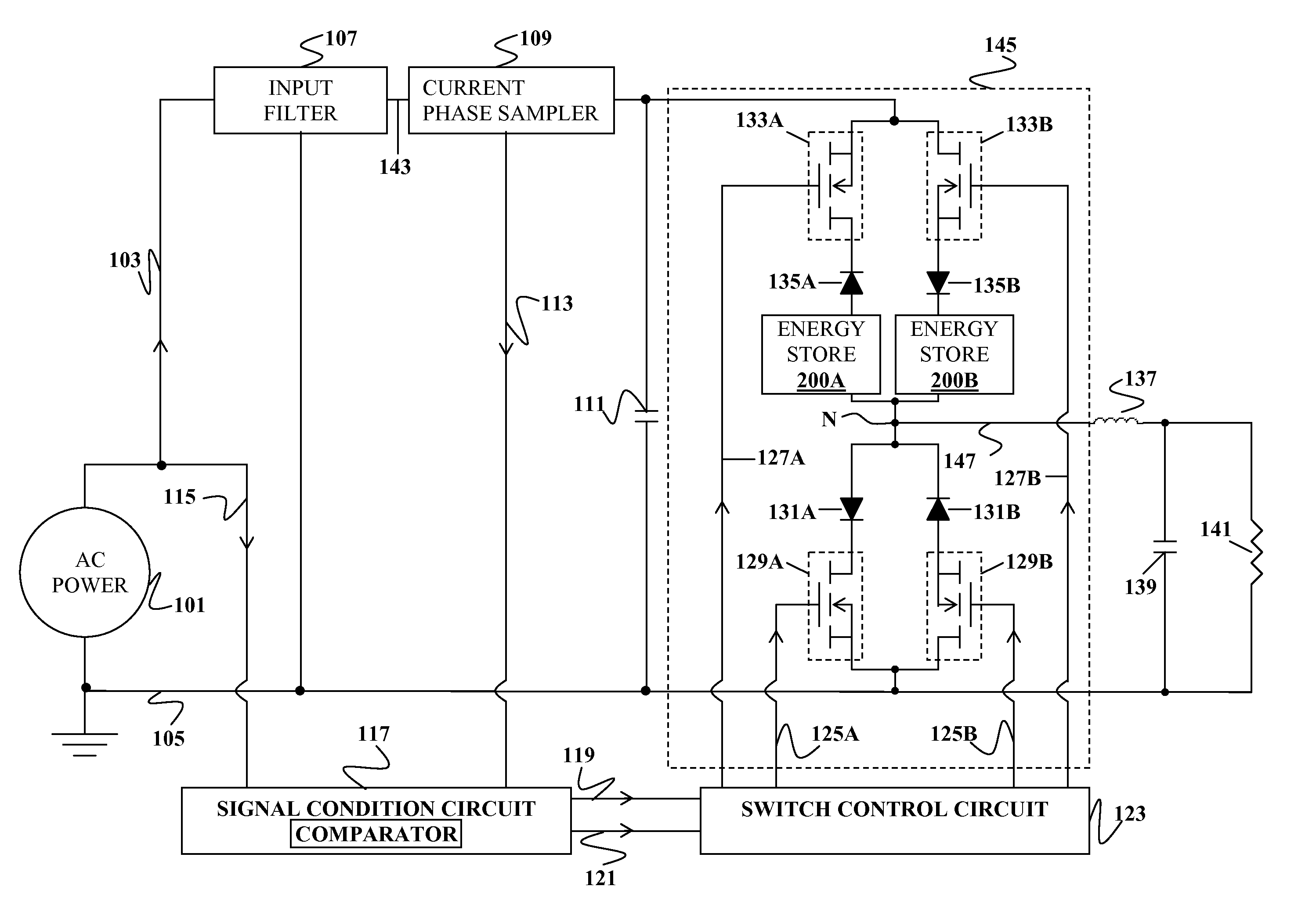
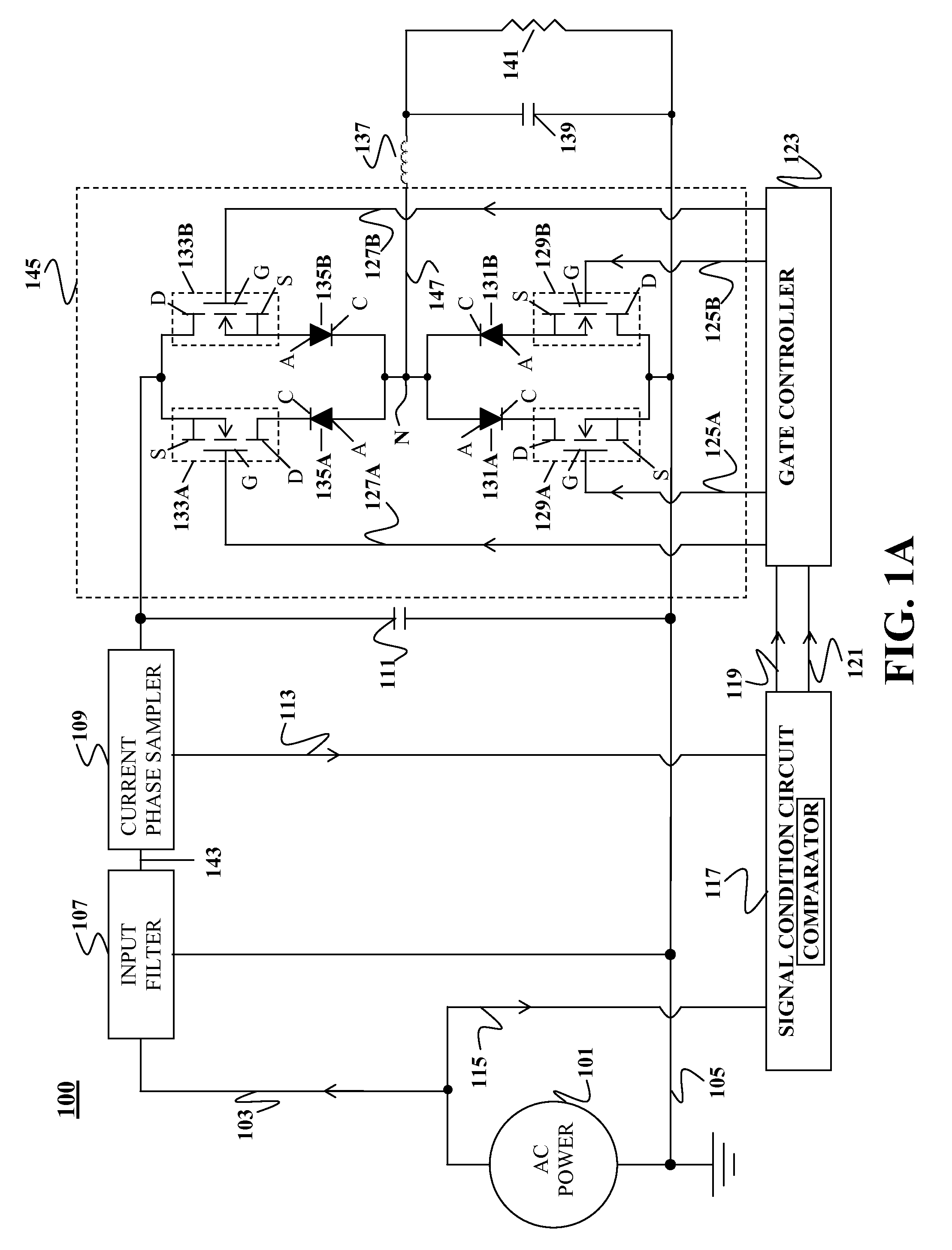
[0023]FIG. 1A is an electrical schematic diagram of a power factor corrector system 100 according to an embodiment of the present invention. In the example depicted in FIG. 1A, AC electrical power supplied to the system 100 by an AC source 101 is of a single phase and exits the AC source 101 via a “live” line 103 and returns to the AC source via a neutral line 105. The live AC voltage 103 is fed into an input filter 107 which may be designed as a low pass filter. The input filter 107 removes transients and high frequency noise from the incoming AC voltage 103 and provides a filtered AC voltage 143 having an optimal attenuation of the AC voltage o...


PUM


Abstract

A voltage control circuit is disclosed. A power factor corrector may utilize the control circuit to provide power factor correction for an AC induction motor. An AC induction motor system may combine the power factor correct with an AC induction motor.

Description

CLAIM OF PRIORITY[0001]This application is a divisional application and claims the priority benefit of U.S. patent application Ser. No. 12 / 203,808 filed Sep. 3, 2008, the entire disclosures of which are incorporated herein by reference.CROSS-REFERENCE TO A RELATED APPLICATION[0002]This application is related to U.S. patent application Ser. No. 08 / 343,887, now U.S. Pat. No. 5,637,975, the entire contents of which are incorporated herein by reference.FIELD OF INVENTION[0003]Embodiments of this invention relate voltage control and more specifically, to power factor correction for alternating current (AC) induction motors.BACKGROUND OF THE INVENTION[0004]Alternating current (AC) induction motors use a large proportion of a given industrialized country's generated electrical power. It is estimated that roughly 70% of the United States' total generator power is used to power motors. To optimize power consumption, it is often desirable for a motor selected for a given application to be abl...

Claims


Application Information

Patent Timeline
Patent Type & Authority Applications(United States)
IPC IPC(8): H02P23/02
CPCG05F1/70H02P23/0081H02J3/1892H02P23/26Y02P80/10H02P27/04
Inventor PUMMER, ALEXANDER
Owner POWERS JOHN E
Why Eureka
Try Eureka