Nth Order Tunable Low-Pass Continuous Time Filter for Fiber Optic Receivers

a fiber optic receiver and continuous time filter technology, applied in the field of optical data links, can solve the problems of high data rate, high cost to use in low cost applications, and not alleviating the need for high capacity optical links with lower cost and simple operation

Active Publication Date: 2010-03-04
LUMENTUM OPERATIONS LLC
View PDF67 Cites 42 Cited by
  • Summary
  • Abstract
  • Description
  • Claims
  • Application Information

AI Technical Summary

Problems solved by technology

However, the complexity of WDM and its higher data rates makes it expensive to use in low cost applications.
While these improvements have marginally increased the data rate, they have not alleviated the need for high capacity optical links with lower cost and simpler operation.
However, current compensation techniques operating in the optical domain are bulky, expensive, and consume too much power.
Moreover, these techniques only compensate for one type of distortion at a time, such as chromatic dispersion, and ignore other types of distortions.
Furthermore, adding optical signal distortion compensators along an optical cable renders the network provisioning process more complicated and significantly increases the network operational expenses.
Additionally, replacing existing lower data rate engineered fiber optic cables with compensated cables to lower distortion and to support higher data rates is very expensive.
These passive components suffer from significant impedance variations, especially in response to process variations.
These impedance variations may adversely affect the the yield of EDC ASICs and reliability of the fiber optic transceivers.
Also, these passive components are unsuitable for on-chip implementations that have significant size constraints.

Method used


Image

  • Nth Order Tunable Low-Pass Continuous Time Filter for Fiber Optic Receivers
  • Nth Order Tunable Low-Pass Continuous Time Filter for Fiber Optic Receivers
  • Nth Order Tunable Low-Pass Continuous Time Filter for Fiber Optic Receivers

Examples


Embodiment Construction

[0040]Embodiments of the invention set forth in the following detailed description generally relate to methods, apparatus, software, and systems for mitigating the distortions, both linear and nonlinear, that affect light pulses as they propagate over an optical fiber medium.

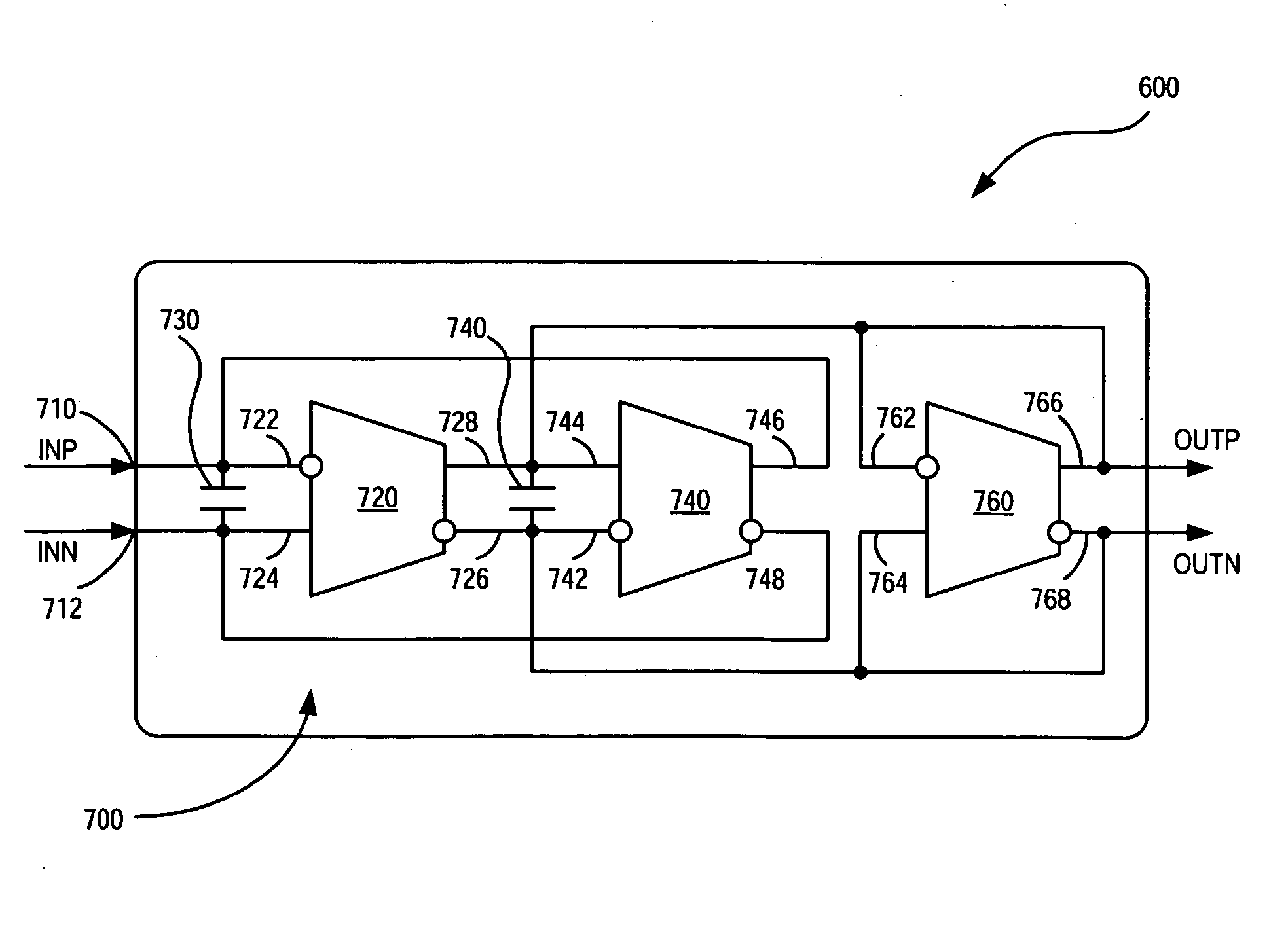
[0041]The embodiments of the invention are directed to a chip system that features a tunable continuous time filter (CTF) that is less susceptible to power supply noise and environmental conditions that tend to increase impedance variations normally found with components used to form the CTF. The CTF comprises differential Operational Transadmittance Amplifiers (OTAs) with optional bias control circuitry along with improved input and output buffers.

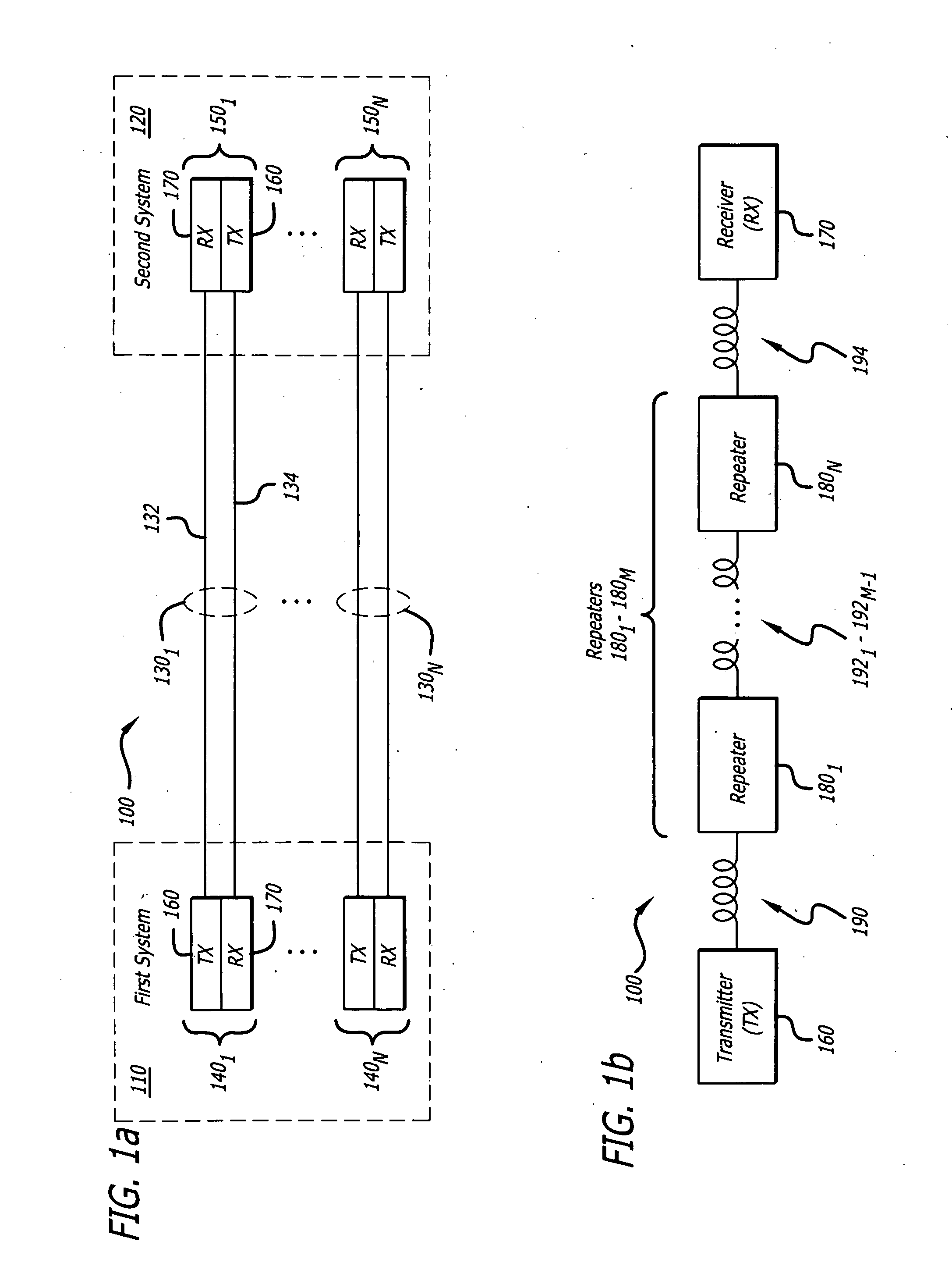
[0042]Referring now to FIG. 1A, a general embodiment of a fiber optic communication system 100 is shown. In the fiber optic communication system 100, a first system 110 is optically coupled to a second system 120 by means of optical communication channels 1301-130N (w...


PUM


Abstract

According to one embodiment of the invention, a circuit comprising a plurality of operational transconductance amplifiers (OTAS) is described. The first OTA has differential input and differential output. The second OTA also has differential input, where a first output of the first OTA is coupled to the first differential input of the second OTA, which is an inverting input. A second output of the first OTA is coupled to the second input of the second OTA, which is a non-inverting input. The first differential output being coupled to a first input of the first OTA and the second differential output being coupled to a second input of the first OTA for negative feedback and current biasing.

Description

FIELD[0001]Embodiments of the invention generally relate to optical data links including wavelength division multiplexing (WDM) fiber optic transmitters, receivers and transceivers. Particularly, embodiments of the invention relate to an Nth order tunable low-pass filter implemented with differential operational transadmittance amplifiers (OTAS) and bias control circuitry.GENERAL BACKGROUND[0002]In order to lower the cost of communications, it has become desirable to increase the data rate and the number of communication channels available. This is particularly true in fiber optic communication systems.[0003]In fiber optic communication systems, wavelength division multiplexing (WDM) has been used over the same fiber optic communication link so that multiple channels of communication may be established over one fiber optic cable. The multiple channels of communication are established at different center wavelengths of light. However, the complexity of WDM and its higher data rates m...

Claims


Application Information

Patent Timeline
Patent Type & Authority Applications(United States)
IPC IPC(8): H03F1/36
CPCH03F3/45085H03F3/45282H03F3/45475H03F2200/453H03H2210/025H03F2203/45138H03F2203/45362H03H11/0433H03H11/0472H03F2203/45134
Inventor BARANAUSKAS, DALIUSZELENIN, DENISBUSSMANN, MATTHIASELAHMADI, SALAM
Owner LUMENTUM OPERATIONS LLC
Why Eureka
Try Eureka