Display Panel and Apparatus Provided with the Same

a technology of display panel and display panel, which is applied in the field of display panel, can solve the problems of spoiling beauty of solar cells, and achieve the effects of improving decorative effect, sophisticated and expensive-looking display panel, and increasing white color ton

Active Publication Date: 2010-03-04
CITIZEN WATCH CO LTD
View PDF11 Cites 10 Cited by
  • Summary
  • Abstract
  • Description
  • Claims
  • Application Information

AI Technical Summary

Benefits of technology

[0061]For the display panel in accordance with the present invention, a pattern in a concave and convex shape is formed on the surface of the reflective polarizing plate. Consequently, in the case in which the display panel is used for a wristwatch of a solar cell driving type for instance, lights of an amount sufficient for an electric power generation in the solar cell can be supplied, and a cross line and a dark purplish color of the solar cell can be prevented from being seen. In addition, an improved design variation and a thin-shaped profile of the display panel can be implemented.
[0062]Moreover, a sophisticated and expensive-looking display panel provided with a metal sense like a metal display panel, a vivid color with whiteness, and an improved decorative effect can be implemented.
[0063]Moreover, a white color tone is increased by forming a diffusing layer on the reflective polarizing plate, whereby a sophisticated and expensive-looking display panel can be obtained.
[0064]Moreover, a display panel having a vivid color with brightness can be obtained by forming a light transmitting colored layer on the reflective polarizing plate.
[0065]Furthermore, the display panel is provided with a plurality of reflective polarizing plates, and the plurality of reflective polarizing plates are disposed in such a manner that the directions of the light transmission easy axes thereof are different from each other. Consequently, an amount of lights supplied to the solar cell can be adjusted simply and easily. As a result, an amount of lights supplied to the solar cell can be adjusted in such a manner that a metal color and a white tone color can appear more intensively on the display panel.
[0066]For the display panel in accordance with the present invention, the light transmitting substrate and the reflective polarizing plate are disposed on a visible side, and a pattern in a concave and convex shape is formed on the surface of the reflective polarizing plate. Consequently, in the case in which the display panel is used for a wristwatch of a solar cell driving type for instance, lights of an amount sufficient for an electric power generation in the solar cell can be supplied, and a cross line and a dark purplish color of the solar cell can be prevented from being seen. In addition, a deep and stereoscopic pattern in a concave and convex shape can be displayed, and an improved design variation of the display panel can be implemented.

Problems solved by technology

Consequently, the solar cell spoils the beauty thereof.

Method used


Image

  • Display Panel and Apparatus Provided with the Same
  • Display Panel and Apparatus Provided with the Same
  • Display Panel and Apparatus Provided with the Same

Examples


embodiment 1

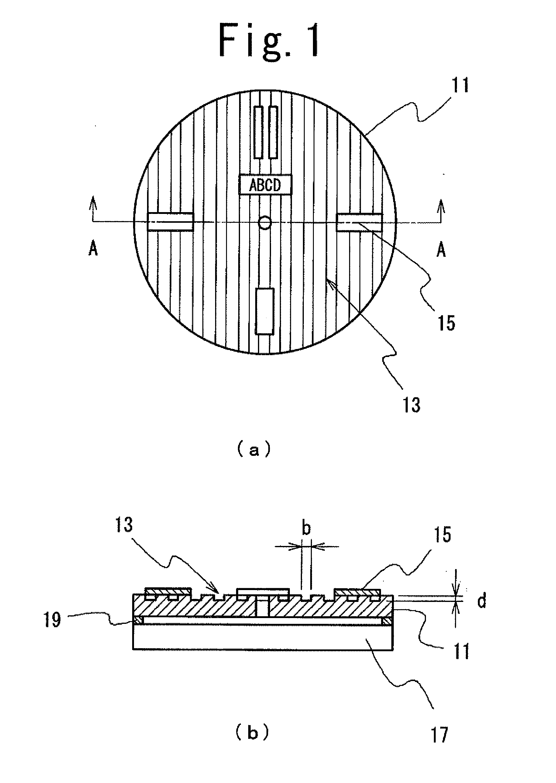
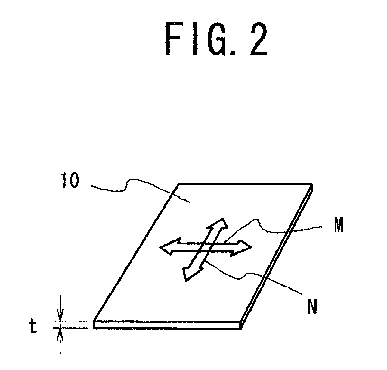
[0220]FIG. 1 is a view showing a display panel in accordance with an embodiment 1 of the present invention. FIG. 1(a) is a plan view, and FIG. 1(b) is a cross-sectional view taken along the line A-A of FIG. 1(a). FIG. 2 is a perspective view showing a reflective polarizing plate substrate. FIG. 3 is a ray diagram showing the path of lights for the display panel.

[0221]As shown in FIG. 1, a display panel in accordance with the embodiment 1 is provided with a solar cell 17 and a reflective polarizing plate 11 disposed on a visible side of the solar cell 17.

[0222]In the embodiment shown in FIG. 1, an axis hole through which a hand spindle driving a minute hand and an hour hand (not shown) penetrates is formed in only the reflective polarizing plate 11. However, an axis hole through which the hand spindle of the movement disposed under the solar cell 17 penetrates is also formed in the solar cell 17 in practice. In the figure, an axis hole of the solar cell 17 is omitted for the sake of ...

embodiment 2

[0246]FIG. 4 is a cross-sectional view showing a display panel in accordance with an embodiment 2 of the present invention.

[0247]As shown in FIG. 4, for the display panel in accordance with the embodiment 2, unlike the embodiment 1, a satin pattern 23 in a concave and convex shape is formed on the surface of a reflective polarizing plate 21 on the side that faces to the solar cell 17 by a method of a transcription from a metal mold. However, other configurations are equivalent to those of the embodiment 1.

[0248]For the reflective polarizing plate 21 in accordance with this embodiment, the operations of a transmission and a reflection of a light are equivalent to those of the reflective polarizing plate 11 described in the embodiment 1.

[0249]For the satin pattern 23 in a concave and convex shape formed on the surface of the reflective polarizing plate 21, a metal color sense and a white color sense of the display panel can be adjusted by varying a size of a concave and a convex.

[0250...

embodiment 3

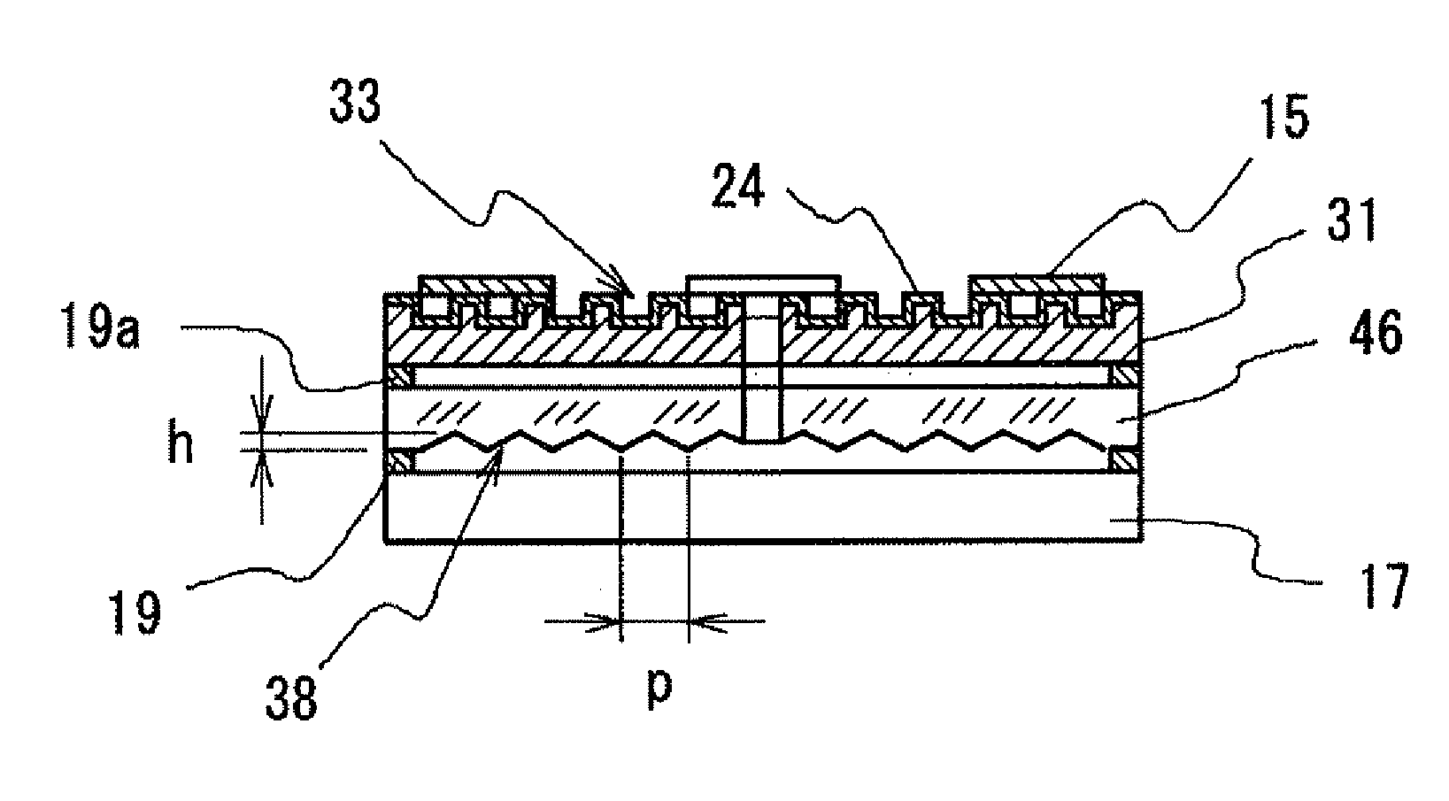
[0262]FIGS. 5 and 6 show a display panel in accordance with an embodiment 3 of the present invention, and an embodiment in which a pattern in a concave and convex shape is formed on the both surfaces of the reflective polarizing plate.

[0263]As shown in FIG. 5, for the display panel in accordance with this embodiment, a lattice pattern 33 in a concave and convex shape is formed on the surface of a visible side of the reflective polarizing plate 31, and a pattern 43 in a concave and convex shape in a circle shape or a spiral shape is formed on the surface on the side that faces to the solar cell 17. The both patterns in a concave and convex shape are formed by a transcription from a metal mold, and can be formed simultaneously on the both surfaces.

[0264]Other configurations are equivalent to those of the embodiment 1. For the reflective polarizing plate 31 in accordance with this embodiment, the operations of a transmission and a reflection of a light are equivalent to those of the re...


PUM


Abstract

A display panel is provided with a solar cell, a light transmitting substrate arranged on a side of the solar cell to be seen, and a reflective polarizing plate. An uneven pattern is arranged on at least one surface of the reflective polarizing plate.

Description

TECHNICAL FIELD[0001]The present invention relates to a display panel including a dial plate for a watch, a parting plate for a clock, and a dial plate for a measuring instrument. More specifically, the present invention relates to a display panel provided with a solar cell on the lower surface side thereof.[0002]Moreover, the present invention relates to an apparatus in which the above display panel is used as a display panel for a clock, a measuring instrument panel of an electronic desk calculator, an automobile, and an airplane, and a display panel of an apparatus like a mobile apparatus such as a cellular phone.BACKGROUND ART[0003]A display panel provided with a solar cell (solar battery) requires an optical transparency so as to transmit a light that has been received and to enable the solar cell disposed on the lower surface side of the display panel to generate an electric power. Therefore, a translucent material such as plastic, ceramic, and glass is used for the display pa...

Claims


Application Information

Patent Timeline
Patent Type & Authority Applications(United States)
IPC IPC(8): G02B5/30G04G21/04
CPCG04G21/04G04C10/02
Inventor OMATA, TERUYUKITAKANO, KOICHIWATANABE, MASAAKIITO, NOBUOYAMAGUCHI, KATSUYUKISAKAMAKI, SHINICHI
Owner CITIZEN WATCH CO LTD
Why Eureka
Try Eureka