
System and method of base station performance enhancement using coordinated antenna array

Active Publication Date: 2010-03-04
AIRHOP COMMUNICATIONS
View PDF15 Cites 123 Cited by
  • Summary
  • Abstract
  • Description
  • Claims
  • Application Information

AI Technical Summary

Benefits of technology

[0016]In a further aspect a method of wireless base station performance enhancement using coordinated beam forming in a wireless network having a plurality of wireless base stations having antenna systems capable of beam forming includes identifying neighboring base stations and configuring the antenna system of two or more of the base stations to create a beam pattern to reduce interference with that neighboring base station.
[0019]A further aspect includes a base station for performance enhancement using coordinated beam forming in a system of base stations. The base station includes an air-interface transceiver system which provides wireless communications with associated subscribers and which performs beam forming and includes an antenna system capable of beam forming; a second receiver configured to perform measurements of signals transmitted by other base stations; and a control unit in communication with the subscriber air-interface system and the second receiver for sending instructions to the subscriber air-interface system for configuring the antenna system of the subscriber air-interface system based upon characteristics of one or more neighboring base stations to create a null beam directed toward a neighboring base station to reduce interference with that neighboring base station.

Problems solved by technology

In the absence of scattering, beam forming results in a well-defined directional pattern, but in general, cellular conventional beams are not a good analogy.
This patent application does not address the issue of coordination of multiple base stations each employs a beam forming systems.

Method used


Image

  • System and method of base station performance enhancement using coordinated antenna array
  • System and method of base station performance enhancement using coordinated antenna array
  • System and method of base station performance enhancement using coordinated antenna array

Examples


Embodiment Construction

[0037]After reading this description, it will become apparent to one skilled in the art how to implement the invention in various alternative embodiments and alternative applications. Although various embodiments of the present invention are described herein, it is understood that these embodiments are presented by way of example only, and not limitation. As such, this detailed description of various alternative embodiments should not be construed to limit the scope or breadth of the present invention.

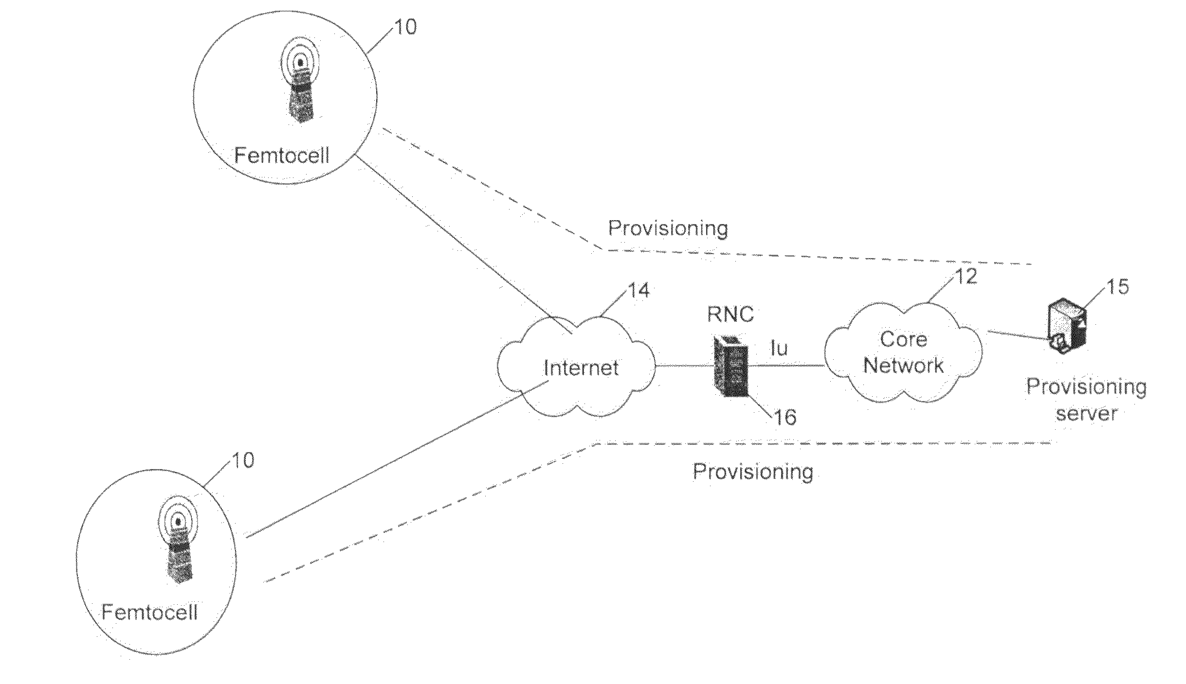
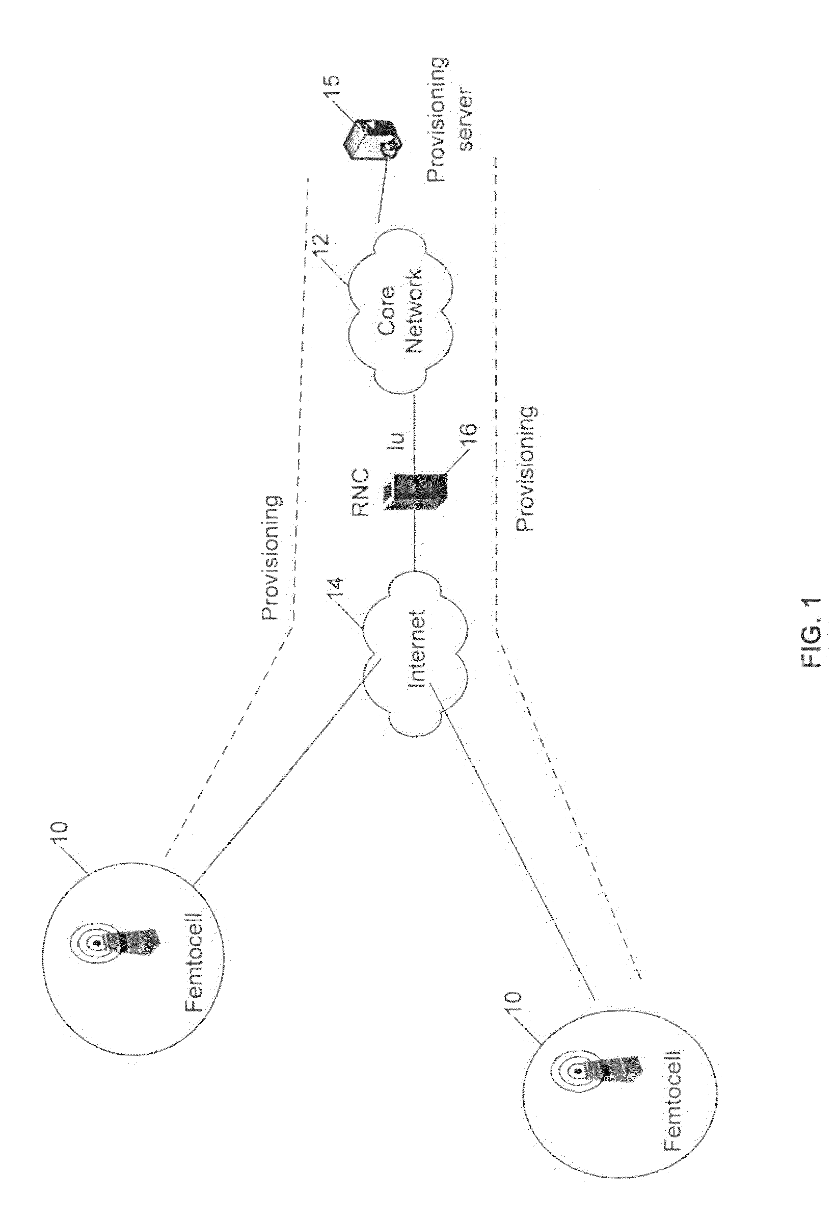
[0038]In a wireless system, a group of base stations (BTSs) can be managed by a centralized network management identity or can be self-organized by communicating with each other via wireless air-interfaces or wired interfaces. The term base station also refers to access points. One such example are Femtocell systems. FIG. 1 shows a Femtocell system where Femtocell BTSs 10 are managed by a core network. Femtocells are connected to core networks 12 over the internet 14 and radio network ...


PUM


Abstract

In wireless system, a group of Basestations (BTSs) can be managed by a centralized network management identity or can be self-organized by communicating with each other via wireless air-interfaces or wired interfaces. One such example are Femtocell systems. When the BTSs are using the same frequency for transmitting and receiving with relatively large transmitting power and when they are closer to each other, performance of such a system and user throughput or QoS (Quality of Service) gets degraded due to the interference between the BTSs and among the users. Smart antenna technique can be used in a coordinated way among a group of BTSs, such as Femtocells, to avoid or reduce interference or manage how interference happens to achieve performance enhancement such as higher system throughput or better QoS to individual applications.

Description

RELATED APPLICATION [0001]The present application claims the benefit of co-pending U.S. provisional patent application No. 61 / 092,679 filed Aug. 28, 2008, the contents of which are incorporated herein by reference in their entirety.FIELD OF THE INVENTION [0002]This invention pertains to wireless communications and to applying smart antenna techniques in a coordinated way among a group of base stations, such as Femtocells, to reduce interference or manage how interference happens.BACKGROUND OF THE INVENTION AND RELATED ART [0003]Antenna arrays provide an efficient way to transmit and receive signals to improve the capacity, data throughput and link range by overcoming undesired channel conditions. Unlike with a single antenna where the parameters are limited to bandwidth, direction and amplitude, the beam pattern for an antenna array can be created by a weight vector which essentially modifies either or both of amplitude and phase of the signal transmitted or received by the antenna....

Claims


Application Information

Patent Timeline
IPC IPC(8): H04W16/00
CPCH04W16/00
Inventor HUI, YAN
Owner AIRHOP COMMUNICATIONS
Learn More