Variable spacing pulse position modulation for ultra-wideband communication links

a technology of ultra-wideband communication and variable spacing, applied in pulse position modulation, pulse technique, digital transmission, etc., can solve the problems of reducing the polarization of the received signal, unable to achieve the optimal performance of binary antipodal signaling, and difficulty in demodulating and decoding signals, so as to reduce the risk of inter-pulse interference, maximize pulse separation, and increase throughput

Active Publication Date: 2006-07-25
WSOU INVESTMENTS LLC +1
View PDF6 Cites 61 Cited by
  • Summary
  • Abstract
  • Description
  • Claims
  • Application Information

AI Technical Summary

Benefits of technology

[0009]The present invention meets the needs described above through a pulse position modulation scheme that allows for a greater throughput than conventional pulse position modulation schemes by maximizing pulse separation and randomizing the time offset between pulses in a time-efficient manner. The present invention provides a novel technique, known as Variable Spacing Pulse Position Modulation (VSPPM), which reduces the risk of inter-pulse interference and guarantees a high spectral density and system throughput. Generally described, the invention includes a method for modulating an ultra-wideband communications signal for transmission across a communications channel. A plurality of data bits are received, each data bit having a first value corresponding to the binary value “0” or a second value corresponding to the binary value “1.” For each set of M data bits that are received, the VSPPM modulator uses a time hopping code sequence to generate a symbol that consists of Nc chips, where each chip has duration Tc and one pulse is transmitted over each chip. Each chip has 2M sub-chip intervals and each sub-chip interval has Np time slots, or time bins. The sub-chip interval and time slot in which the pulse resides are determined by the set of M input data bits and a time hopping code sequence value, respectively. The sub-chip interval is chosen based on a pre-determined one-to-one mapping between the set of possible M-tuples and the 2M sub-chip intervals. The time hopping code sequence comprises Nc elements with each element taking integer values from 0 to (Np−1). In general, the time hopping sequence to be used may be chosen from a set of possible time hopping sequences based on the value of the M-tuple (i.e., symbol value). The same hopping sequence may be used for all symbol values (M-tuples) or alternatively, a unique time hopping sequence may be used for each symbol value.

Problems solved by technology

While the UWB properties described above are desirable for covert communications and help reduce interference, they make it difficult to demodulate and decode the signal.
Unfortunately, binary antipodal signaling provides adequate performance only when the distortion to the signal is minimal.
In addition, adequately resolving the polarization of the received signals is a particularly challenging issue in a high multi-path delay spread environment.
Typically, complex receivers are required to resolve the polarization of each pulse, thereby adding to the cost and complexity of the system.
Although OOK modulation is simple to implement for both modulation and demodulation, OOK is vulnerable to additive noise in the channel.
This has several drawbacks for UWB systems.
As a result, the large PPM modulation pulse spacing can severely limit system throughput.

Method used


Image

  • Variable spacing pulse position modulation for ultra-wideband communication links
  • Variable spacing pulse position modulation for ultra-wideband communication links
  • Variable spacing pulse position modulation for ultra-wideband communication links

Examples


Embodiment Construction

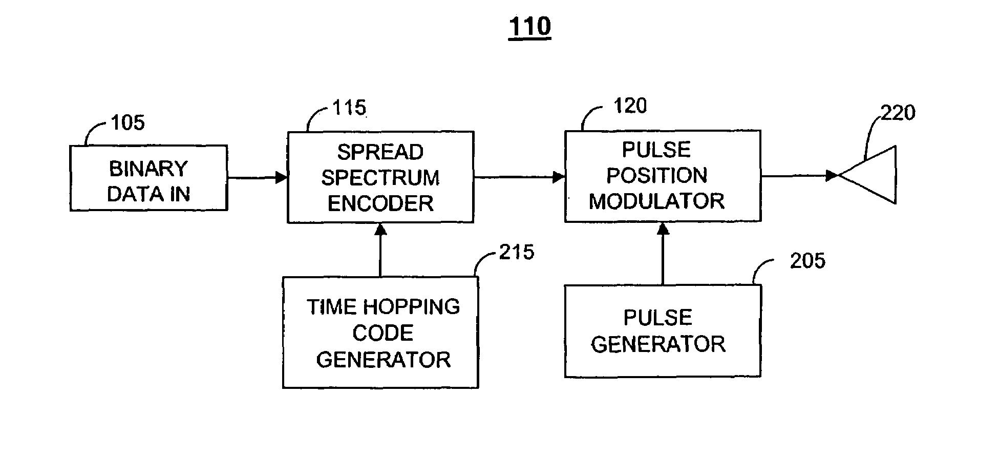
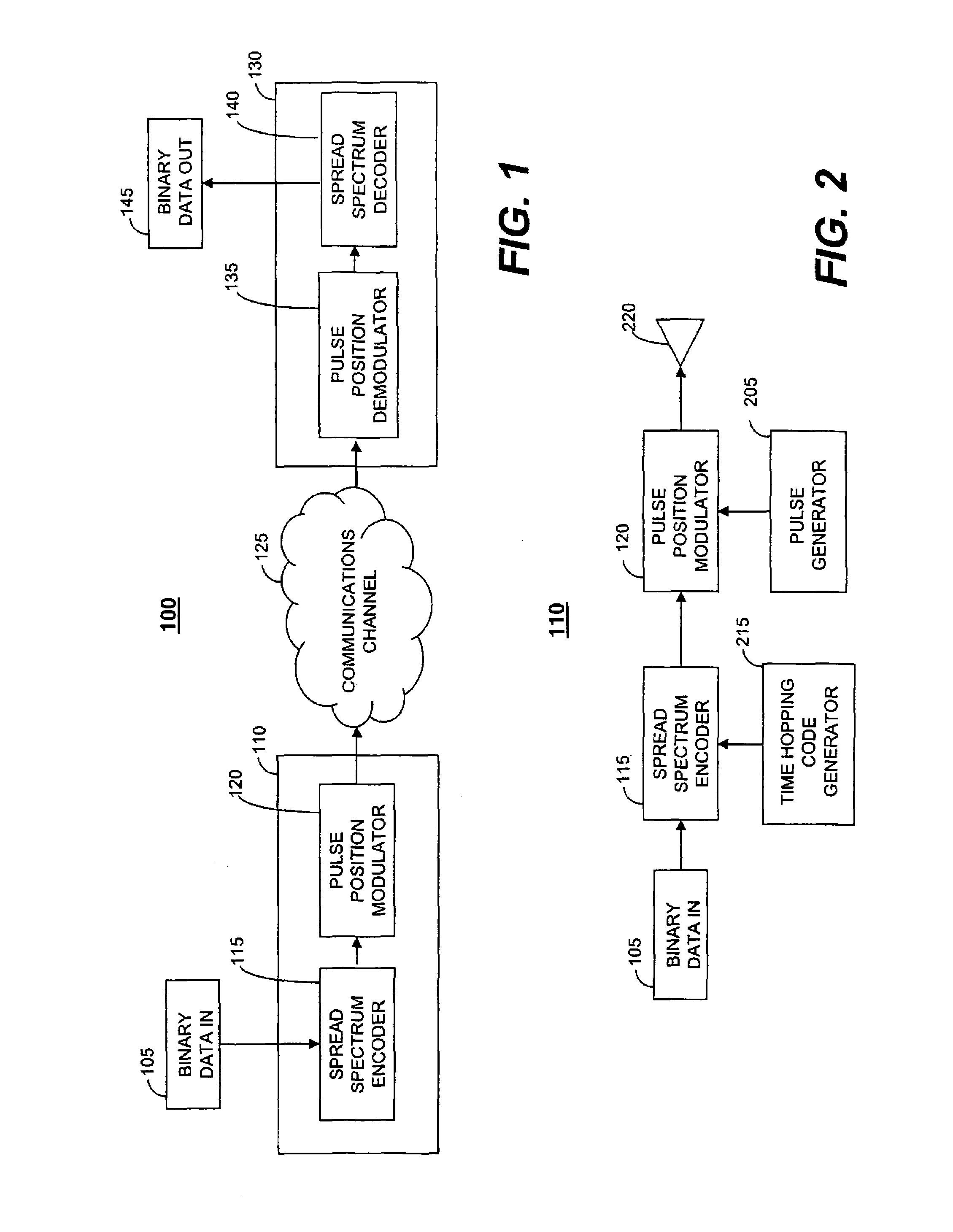
[0018]The present invention is typically embodied in a communications scheme for modulating ultra-wideband (UWB) signals. The present invention is a new modulation technique, called Variable Spacing Pulse Position Modulation (VSPPM), which reduces the risk of inter-pulse interference and guarantees high spectrum efficiency. The VSPPM scheme maximizes the average separation between modulated pulses to achieve greater resistance to large delay spreads. In addition, VSPPM randomizes the time offset between adjacent pulses to provide greater immunity to multiple access interference. As a result, the bandwidth efficiency of UWB communications systems is increased.

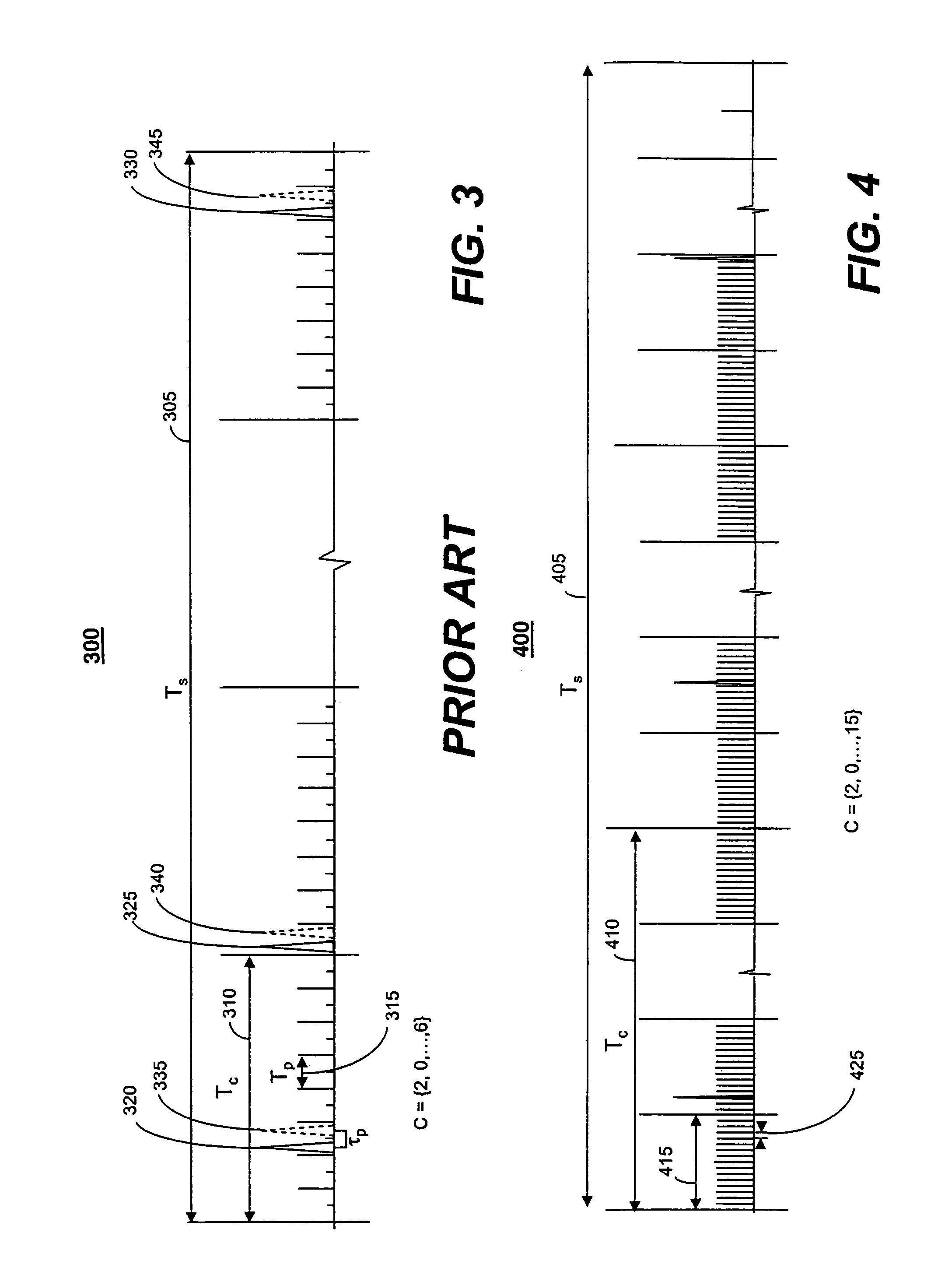
[0019]The VSPPM scheme can be used to mitigate the effects of channel dispersion in traditional time-hopped code division multiple access systems (TH-CDMA). In a typical TH-CDMA system using conventional pulse position modulation (PPM), the modulated pulse “hops” over a set of Np positions within each chip of the transmitted sym...


PUM


Abstract

Methods and systems for generating a variable spacing pulse position modulated (VSPPM) signal for transmission across an ultra-wideband communications channel. The variable pulse position modulated spread spectrum signal is created by encoding every M input data bits from an input data stream into a symbol consisting of Nc chips. Each chip is divided into 2M sub-chips and each sub-chip is further divided into Np time slots. A pulse is transmitted for each chip in the symbol. During each chip period, the pulse is placed in the sub-chip corresponding to the binary M-tuple (or symbol) value. A time hopping code sequence consisting of Nc elements with a one-to-one chip association is then applied to each symbol so that the position of each pulse is shifted to the appropriate time slot that corresponds to the time hopping code value.

Description

TECHNICAL FIELD[0001]This invention relates to ultra-wideband communications systems and, more particularly, relates to randomly varying the spacing between pulse position modulated pulses.BACKGROUND OF THE INVENTION[0002]Ultra-wideband technology has several unique and attractive features, such as immunity to multi-path interference, jamming, and intentional and unintentional interference, low probability of intercept, and enhanced penetration capabilities. Additionally, the elimination of radio frequency (RF) components from the UWB transceivers enables the use of devices with relatively low hardware complexity. Nanosecond pulse durations also make it attractive for application such as precision geo location. As a result, UWB technology is currently being considered for the support of robust, scalable networks that will support a wide range of military and commercial applications in harsh environments (e.g., high multi-path fading, high jamming, and high interference environments)...

Claims


Application Information

Patent Timeline
Patent Type & Authority Patents(United States)
IPC IPC(8): H04B1/69H03K7/04H04B7/212H04L25/49
CPCH04B1/7176H04L25/4902H04B2001/6908
Inventor BALACHANDRAN, KRISHNACALIN, DORUJI, TINGFANGKANG, JOSEPH H.
Owner WSOU INVESTMENTS LLC
Why Eureka
Try Eureka