Radiographic imaging system, radiographic imaging device, control device, and radiographic imaging control method

a radiographic imaging and control device technology, applied in the direction of material analysis using wave/particle radiation, instruments, applications, etc., can solve the problems of the communication state becomes unstable, and the radiation that is irradiated up to the transition to the charge accumulating state is wasted, etc., to achieve the effect of stab captur

Active Publication Date: 2010-03-04
FUJIFILM CORP
View PDF0 Cites 11 Cited by
  • Summary
  • Abstract
  • Description
  • Claims
  • Application Information

AI Technical Summary

Benefits of technology

[0011]The present invention was made in view of the above-described circumstances, and an object thereof is to provide a radiographic imaging system, a radiographic imaging device, a control device, and a radiographic imaging control method that can carry out capturing of a radiographic image stably even in cases in which communication between a radiographic imaging device and a control device is wireless communication.
[0048]In accordance with the present invention, a radiographic imaging device transmits, plural times and by wireless communication and even during a response wait time period, imaging start instructing information that instructs starting of imaging at a time when preparations for capturing a radiographic image have been completed. A control device controls a radiation irradiating section such that radiation is irradiated with respect to the radiographic imaging device in a case in which any of the imaging start instructing information that are transmitted plural times is received. Therefore, the present invention has the effect that radiographic images can be captured stably even in cases in which the communication between the radiographic imaging device and the control device is wireless communication.

Problems solved by technology

In cases in which the communication between the electronic cassette and the console is wireless communication, there are cases in which the state of the communication becomes unstable and the console receives the instruction information late or cannot receive the instruction information.
However, in the technique of JP-A No. 2008-132216, even if the start of irradiation of X-rays is sensed during the resetting operation, it is not possible to immediately transition to the charge accumulating state, and the radiation that is irradiated up to the transition to the charge accumulating state is wasted.

Method used


Image

  • Radiographic imaging system, radiographic imaging device, control device, and radiographic imaging control method
  • Radiographic imaging system, radiographic imaging device, control device, and radiographic imaging control method
  • Radiographic imaging system, radiographic imaging device, control device, and radiographic imaging control method

Examples


first exemplary embodiment

[0062]First, the structure of a radiation information system 10 relating to a first exemplary embodiment will be described.

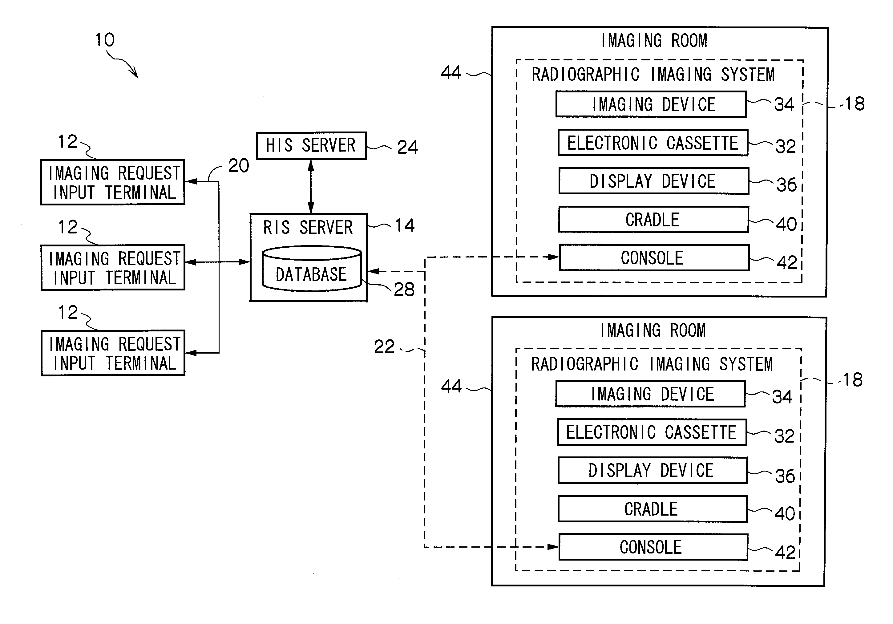
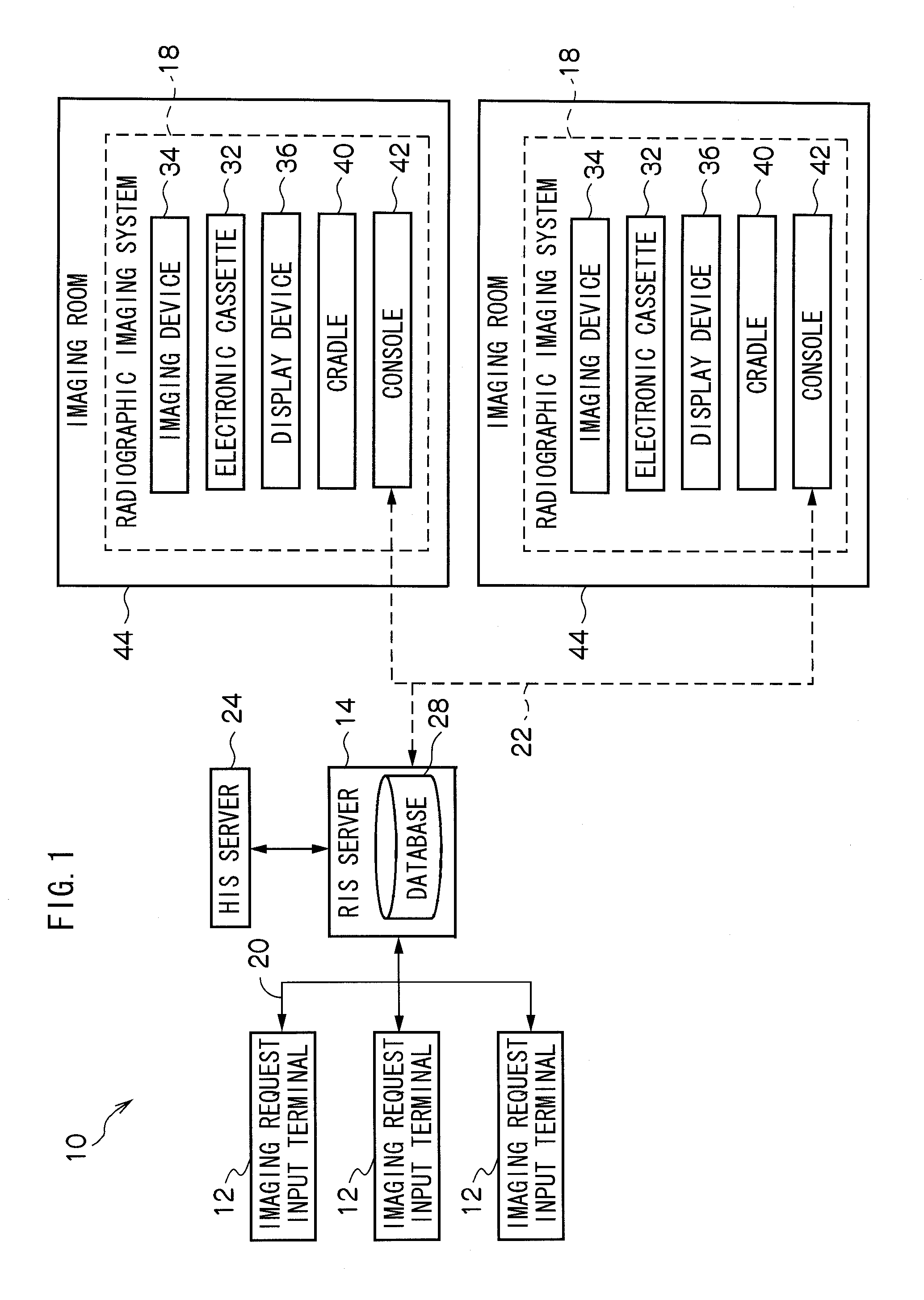
[0063]A block diagram showing the respective structural elements of the radiation information system 10 (hereinafter also called “RIS 10”) relating to the present exemplary embodiment is shown in FIG. 1.

[0064]The RIS 10 is a system for carrying out information management such as scheduling of examinations / treatments, recording of diagnoses, and the like in a radiology department, and structures a part of a hospital information system (HIS).

[0065]The RIS 10 is structured to include plural imaging request input terminals 12 (hereinafter also called “input terminals 12”), an RIS server 14, and plural radiographic imaging systems 18 (hereinafter also called “imaging systems 18”).

[0066]The RIS server 14 manages the entire RIS 10, and is structured such that communication between the respective input terminals 12 and the imaging systems 18 is possible by LAN (Local Ar...

second exemplary embodiment

[0140]A second exemplary embodiment of the present invention will be described next.

[0141]Because the structure of the radiation information system 10 and the structure of the electronic cassette 32 relating to the second exemplary embodiment are the same as those of the above-described first exemplary embodiment (see FIG. 1 through FIG. 6), description thereof will be omitted here.

[0142]A timing chart showing the flow of operations at the time of capturing a radiographic image by the imaging system 18 relating to the second exemplary embodiment is shown in FIG. 10. Note that portions that are the same as those of the above-described first exemplary embodiment (FIG. 7) are denoted by the same reference numerals, and description thereof is omitted.

[0143]The electronic cassette 32 relating to the present exemplary embodiment as well transmits the instruction information C8, that instructs starting of imaging and includes identification information for identifying which time number (i....

third exemplary embodiment

[0150]A third exemplary embodiment of the present invention will be described next.

[0151]Because the structure of the radiation information system 10 and the structure of the electronic cassette 32 relating to the third exemplary embodiment are the same as those of the above-described first exemplary embodiment (see FIG. 1 through FIG. 6), description thereof will be omitted here.

[0152]A timing chart showing the flow of operations at the time of capturing a radiographic image by the imaging system 18 relating to the third exemplary embodiment is shown in FIG. 11. Note that portions that are the same as those of the above-described first exemplary embodiment (FIG. 7) are denoted by the same reference numerals, and description thereof is omitted.

[0153]In the present exemplary embodiment, when an exposure condition designating operation is carried out with respect to the operation panel 102, the console 42 transmits the exposure condition information C2, such as the tube voltage, the t...


PUM

PropertyMeasurementUnit
radiographic imagingaaaaaaaaaa
timeaaaaaaaaaa
transmissionaaaaaaaaaa

Abstract

There is provided a radiographic imaging system including: a radiographic imaging device including a generating section that captures a radiographic image expressed by irradiated radiation and generates image information expressing the captured radiographic image, and a first communication section that transmits, plural times and by wireless communication and even during a response wait time period, imaging start instructing information that instructs starting of imaging when preparations for capturing a radiographic image by the generating section have been completed; and a control device having a second communication section that can communicate by wireless communication with the first communication section, and a control section that controls a radiation irradiating section such that radiation is irradiated with respect to the radiographic imaging device in a case in which the second communication section receives any of the imaging start instructing information that are transmitted plural times from the first communication section.

Description

CROSS-REFERENCE TO RELATED APPLICATIONS[0001]This application is based on and claims priority under 35 USC 119 from Japanese Patent Applications No. 2008-219935 filed on Aug. 28, 2008 and No. 2009-081992 filed on Mar. 30, 2009, the disclosures of which are incorporated by reference herein.BACKGROUND[0002]1. Technical Field[0003]The present invention relates to a radiographic imaging system, a radiographic imaging device, a control device, and a radiographic imaging control method.[0004]2. Related Art[0005]FPDs (Flat Panel Detectors), in which a radiation-sensitive layer is disposed on a TFT (Thin Film Transistor) active matrix substrate and that can convert radiation directly into digital data, have been put into practice in recent years. Portable radiographic imaging devices (hereinafter also called “electronic cassettes”), that generate image information expressing a radiographic image manifested by radiation irradiated by using an FPD or the like and that store the generated imag...

Claims


Application Information

Patent Timeline
Patent Type & Authority Applications(United States)
IPC IPC(8): G01N23/04H05G1/56
CPCG01N23/04A61B6/4494A61B6/548
Inventor KITANO, KOUICHITSUBOTA, KEIJIYOSHIDA, YUTAKANARIYUKI, FUMITOOHTA, YASUNORINISHINO, NAOYUKI
Owner FUJIFILM CORP
Why Eureka
Try Eureka