Airfoil insert

a technology of air intake and air filter, which is applied in the direction of machines/engines, stators, liquid fuel engines, etc., can solve the problems of reducing service life and reliability, increasing thermal and mechanical loads, and high combustion temperatures, so as to reduce the reynolds number of convective flow, increasing the heat transfer coefficient of convective flow, and reducing the noise of low-bypass turbofans

Inactive Publication Date: 2010-03-04
UNITED TECH CORP
View PDF22 Cites 77 Cited by
  • Summary
  • Abstract
  • Description
  • Claims
  • Application Information

AI Technical Summary

Benefits of technology

[0011]The contact element is formed on the exterior of the insert wall between the first end and the second end, for attaching the insert to an airfoil and for spacing the insert wall from the internal airfoil surfaces. The flow director is formed on the insert wall at a boundary between the exterior and interior, and increases the heat transfer coefficient of convective flow along the insert by directing the convective flow to th

Problems solved by technology

Low-bypass turbofans are louder and less fuel efficient, but provide greater response and specific thrust.
Unfortunately, high combustion temperatures also increase thermal and mechanica

Method used


Image

  • Airfoil insert
  • Airfoil insert
  • Airfoil insert

Examples


Embodiment Construction

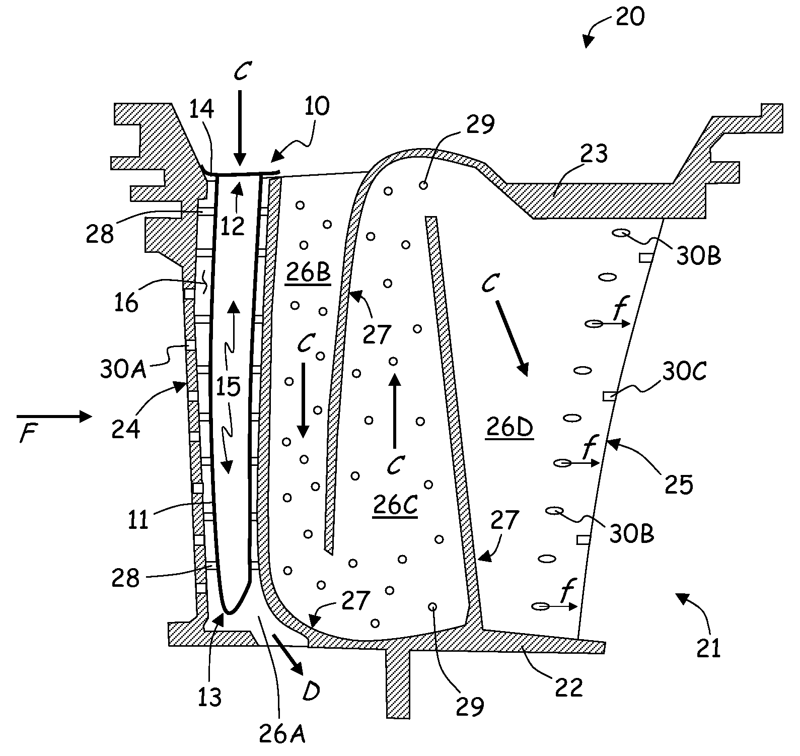
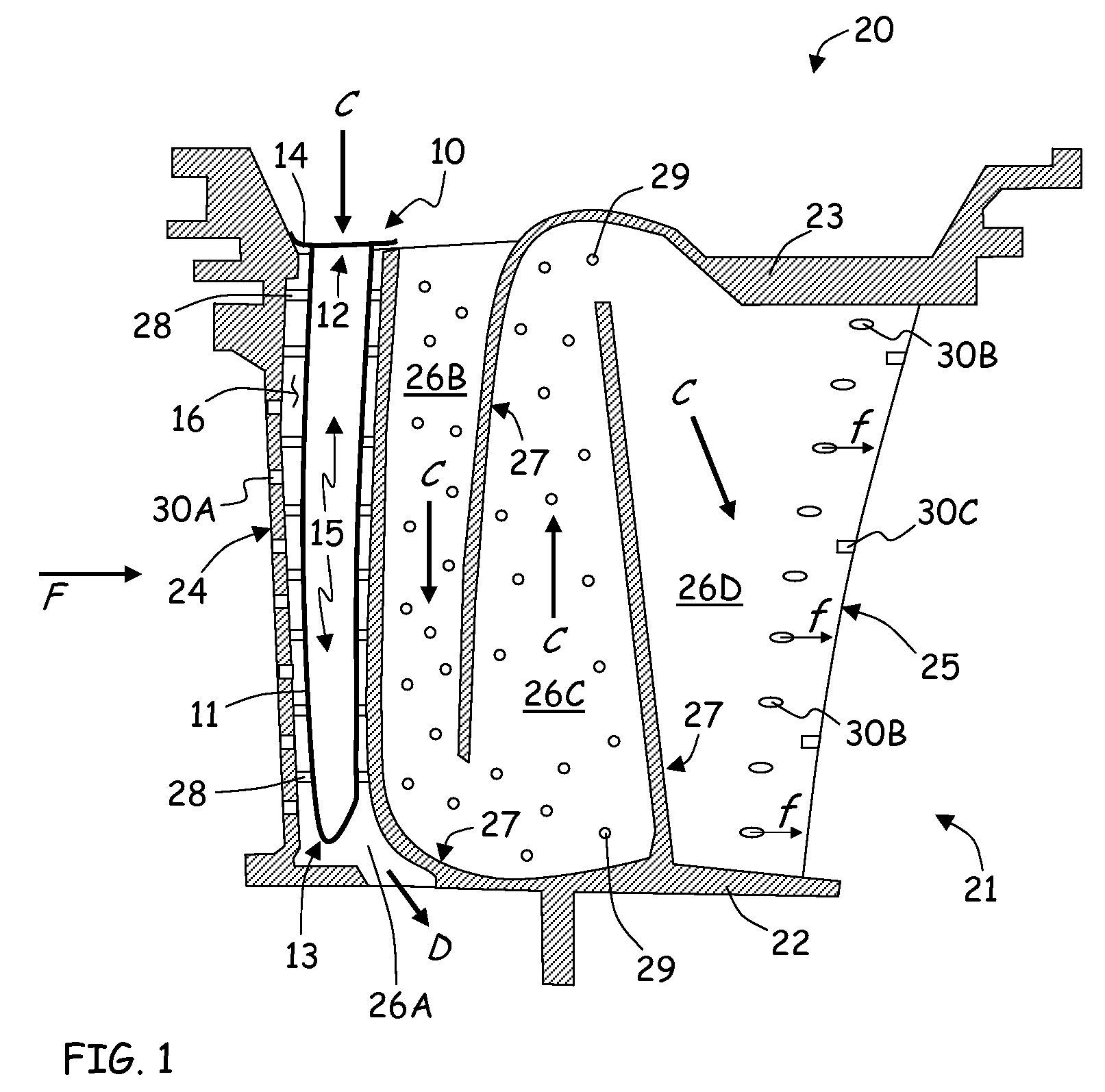
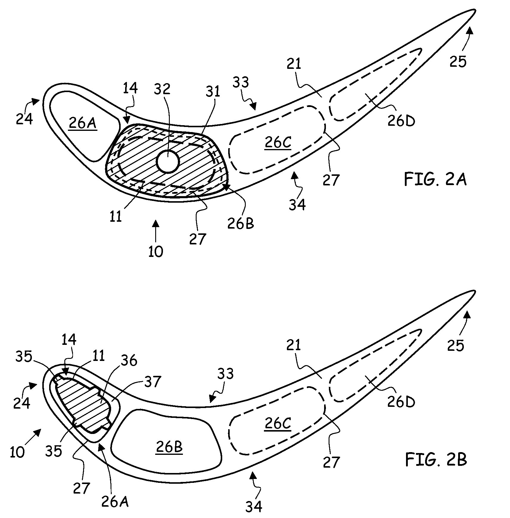
[0024]FIG. 1 is a cross-sectional schematic of insert 10 for airfoil 20. Insert 10 comprises insert wall 11 with first end 12, second end 13 and contact element 14 for attaching insert 10 to airfoil 20 and for positioning insert wall 11 within airfoil section 21. Insert 10 increases the heat transfer coefficient of convective flow by directing the convective flow around insert wall 11, away from internal region 15 and into external region 16, between insert wall 11 and airfoil section 21.

[0025]Airfoil 20 comprises airfoil section 21, inner platform 22 and outer platform 23. Airfoil section 21 extends axially between leading edge 24 and trailing edge 25, and radially between platforms 22 and 23. Internal cooling passages 26A, 26B, 26C and 26D are defined along internal surfaces 27 of airfoil section 21. Augmentors such as trip strips 28 and pedestals 29 are formed along internal surfaces 27 of passages 26A, 26B and 26C, in order to increase turbulence and improve internal cooling. Fi...


PUM


Abstract

An airfoil insert comprises an insert wall, a contact element and a flow director. The insert wall defines an interior extending inside the insert wall from a first end to second end, and an exterior extending outside the insert wall from the first end to the second end. The contact element is formed on the exterior of the insert wall. The flow director is formed on the insert wall at a boundary between the interior and the exterior. The flow director increases a heat transfer coefficient of convective flow along the insert wall by directing the convective flow to the exterior of the insert wall.

Description

BACKGROUND OF THE INVENTION[0001]The subject matter of this application relates generally to gas turbine engines, and specifically to cooling techniques for the airfoil sections of turbine blades and vanes. In particular, the invention concerns an insert for convective cooling the interior surfaces of turbine airfoils exposed to high-temperature working fluid flow.[0002]Gas turbine engines are built around a power core comprising a compressor, a combustor and a turbine, which are arranged in flow series with a forward (upstream) inlet and an aft (downstream) exhaust. The compressor compresses air from the inlet, which is mixed with fuel in the combustor and ignited to produce hot combustion gases. The hot combustion gases drive the turbine section, and are exhausted with the downstream flow.[0003]The turbine drives the compressor via a shaft or a series of coaxially nested shaft spools, each driven at different pressures and speeds. The spools employ a number of stages comprised of ...

Claims


Application Information

Patent Timeline
IPC IPC(8): F04D29/58F01D25/12F01D5/18
CPCF01D5/189F05D2260/202Y02T50/676Y02T50/67Y02T50/60
Inventor DEVORE, MATTHEW A.KAUFMAN, ELEANOR D.SURACE, RAYMONDABDEL-MESSEH, WILLIAM
Owner UNITED TECH CORP
Why Eureka
Try Eureka