Resistive contact sensors for large blade and airfoil pressure and flow separation measurements

a technology of resistive contact and sensor, which is applied in the direction of instruments, liquid fuel engines, machines/engines, etc., can solve the problems of preventing the pressure measurement from being used in the production of wind turbines, and the directionality of the pressure measurement to be further limited

Inactive Publication Date: 2010-03-04
GENERAL ELECTRIC CO
View PDF5 Cites 15 Cited by
  • Summary
  • Abstract
  • Description
  • Claims
  • Application Information

AI Technical Summary

Benefits of technology

[0007]According to another aspect of the present invention, a method adapted to using fluid dynamic resistive contact sensors for measurement of fluid dynamic parameters related to wind turbine blade performance is provided. The method includes arranging the fluid dynamic resistive contact sensors, which may be comprised of a pressure-sensitive conductive composite material formed of a polymer and a conductive filler, according to a predetermined pattern on the surface of a wind turbine blade. The method further includes mounting the fluid dynamic resistive contact sensors on the wind turbine blade to maintain the sensors fixed in place during rotation of the wind turbine blade in wind turbine operation. The method also establishes means for communicating electrically between the fluid dynamic resistive contact sensors mounted on the blade and a data acquisition terminal.

Problems solved by technology

This prevents the pressure measurement from being employed in production wind turbines.
With such instrumentation, the pressure typically needs to be introduced into the sensor diaphragm by a nozzle and a tube, causing the directionality of the pressure measurement to be further limited.

Method used


Image

  • Resistive contact sensors for large blade and airfoil pressure and flow separation measurements
  • Resistive contact sensors for large blade and airfoil pressure and flow separation measurements
  • Resistive contact sensors for large blade and airfoil pressure and flow separation measurements

Examples


Embodiment Construction

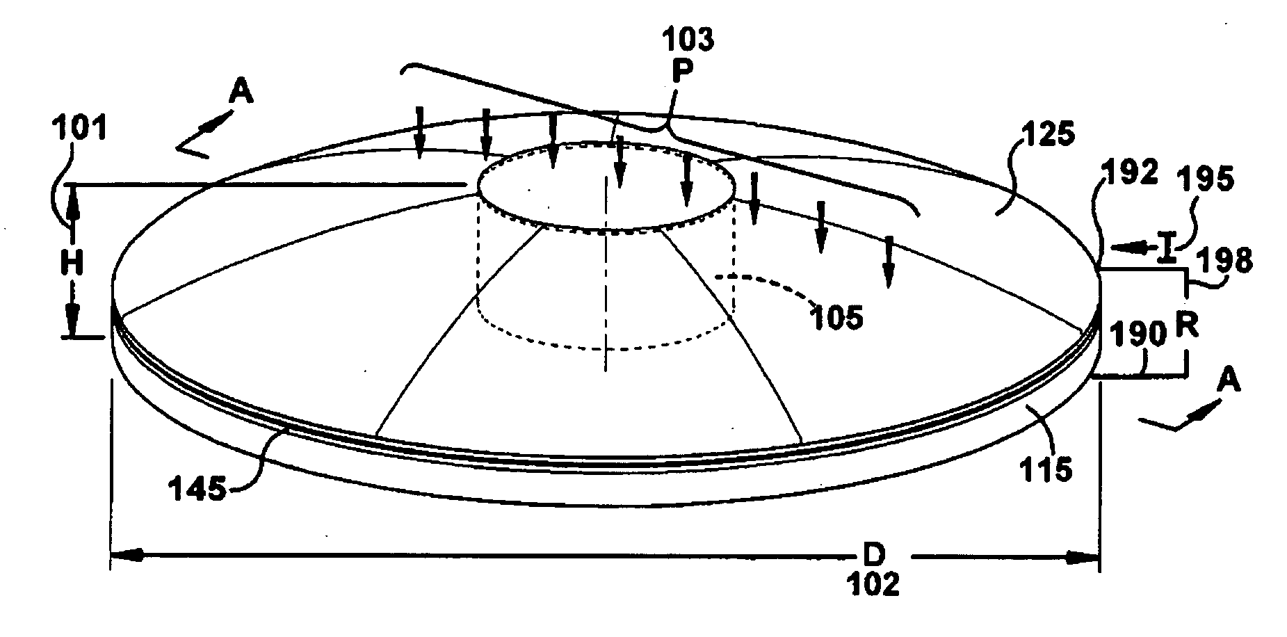
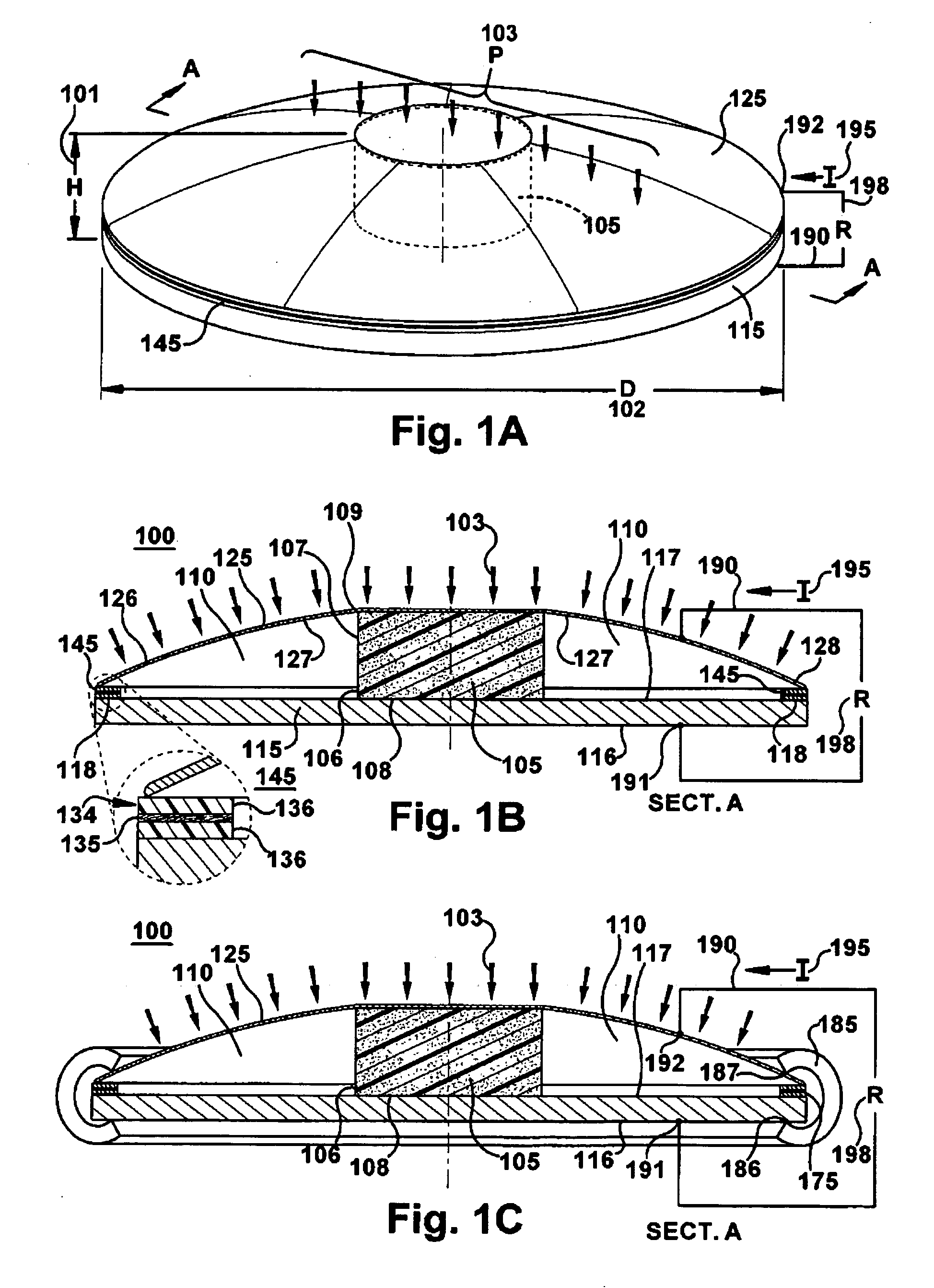
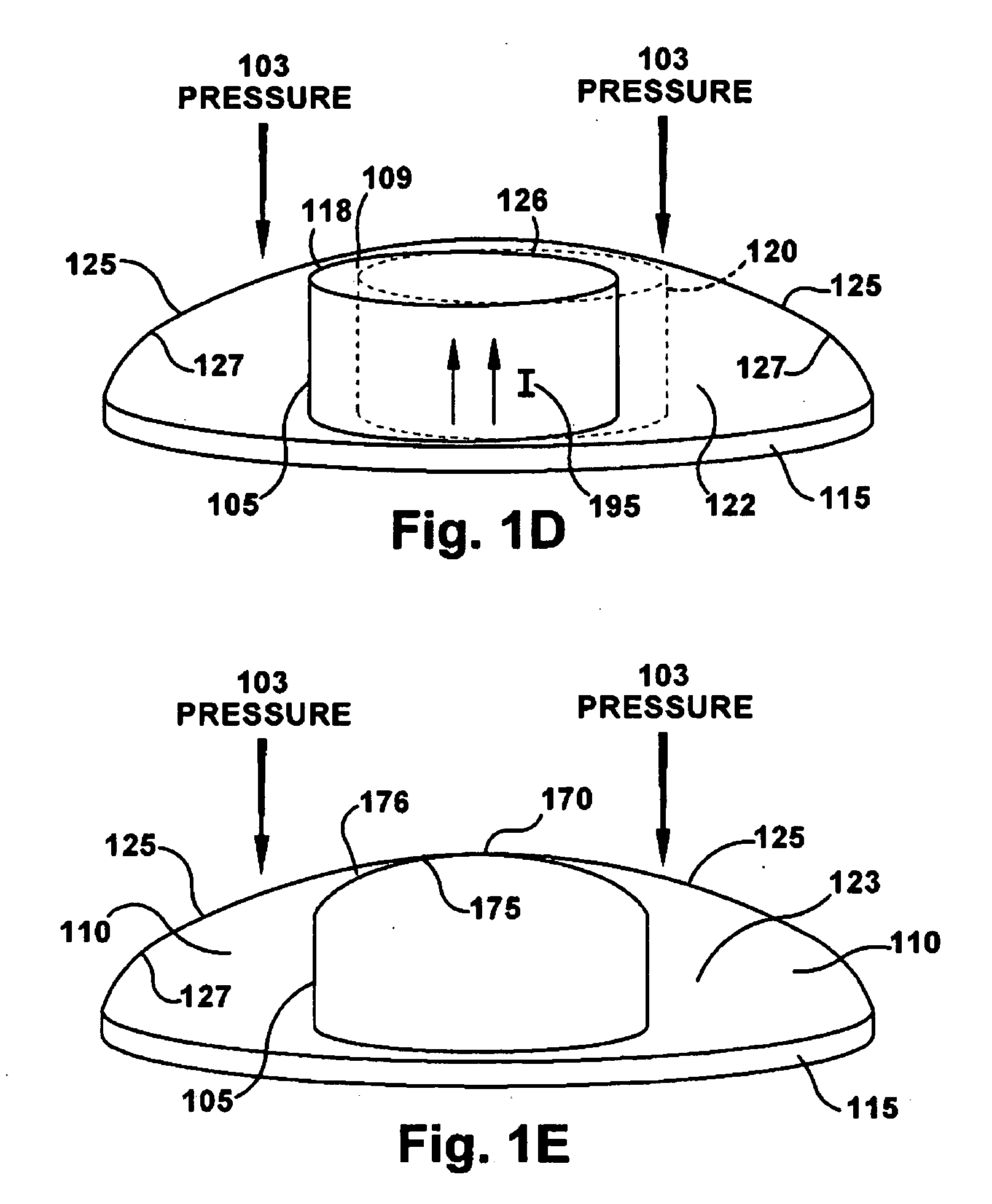
[0035]The following embodiments of the present invention have many advantages, including offering pressure sensors as thin streamlined patches on the turbine blade that do not impact the blade structure and fluid dynamic characteristics. The sensors permit the elimination of port and tubes, eliminating hysteresis, damping directionality and providing increased frequency response relative to previous mechanical pressure measurements, thereby achieving a more accurate measurement. Further the thin patches of the sensor may permit incorporation into the blade surface for real time wind turbine performance measurement and real time turbine control capabilities. Additionally, the contact patches may be applied to the surface for diagnostic and validation purposes.

[0036]Recently, various contact sensors have been developed, which include a conductive composite material formed of a polymer and a conductive filler. The composite materials of the contact sensor may have physical characterist...


PUM


Abstract

A wind turbine blade instrumentation structure and method is provided for fluid dynamic polymer-based contact sensors measuring ambient pressure based on the resistivity changes across the sensor. The pressure sensors may applied in predetermined patterns to airfoil structures, such as wind turbine blades, without impacting the blade structure and fluid dynamic characteristics. The pressure sensors measure blade performance with high fidelity. The pressure measurements are transmitted to processing to determine blade characteristics and environment including flow separation, stagnation point, angle of attack, lift and drag and wind speed. Further processing of the pressure distribution may identify wind shear, up-flow and yaw error.

Description

RELATED APPLICATION[0001]This application is related to and claims benefit from U.S. provisional application 61 / 091,928 by Danian Zheng et al., filed on Aug. 26, 2008. This application is also related to Docket 233329-2 by Danian Zheng et al, filed on Sep. 25, 2008.BACKGROUND OF THE INVENTION[0002]The application relates generally to large blades and airfoils, and more specifically to sensors and instrumentation of wind turbine blades for blade performance measurements.[0003]Measurement of blade fluid dynamic parameters for airfoils in general and wind turbine blades in particular have usually employed traditional methods of mechanical pressure detection. Such pressure detectors include piezo / strain-based pressure sensors that require a diaphragm to measure the pressure-induced stress and strain. Sizable ducts or penetrations are required in the airfoil or blade structure to accommodate the diaphragm package. This prevents the pressure measurement from being employed in production w...

Claims


Application Information

Patent Timeline
Patent Type & Authority Applications(United States)
IPC IPC(8): F04D29/00
CPCG01L9/0058Y02E10/721G01M9/06G01L9/008Y02E10/72
Inventor ZHENG, DANIANGERBER, BRANDON S.MAGNUSON, DAVID C.WILLEY, LAWRENCE D.
Owner GENERAL ELECTRIC CO
Why Eureka
Try Eureka