
Method to signficantly increase electrophoretic coating thickness and/or to provide a conductive electrophoretically coated surface

a technology of electrophoretic coating and coating surface, which is applied in the direction of fluid pressure measurement, liquid/fluent solid measurement, peptide, etc., can solve the problems of porous coating, coating with pores or breaks, and inacceptable aesthetic and functional perspectives, so as to achieve thicker coatings and thin coatings

Inactive Publication Date: 2010-03-04
DELPHI TECH INC
View PDF0 Cites 5 Cited by
  • Summary
  • Abstract
  • Description
  • Claims
  • Application Information

AI Technical Summary

Benefits of technology

[0011]The invention, in one of its aspects, allows the use of conventional electrophoretic coating compositions and / or processing equipment to achieve thicker coatings. In addition, the invention allows thicker coatings to be achieved with conventional electrophoretic coating processing parameters (e.g., pH, temperature, voltage, etc.).

Problems solved by technology

Currently, most electrophoretic coating processes have a coating thickness limitation of from about 0.5 mil (12.7 micrometer) to 1 mil (25.4 micrometer).
This limitation is due to the fact that most electrophoretic coatings are naturally electrically insulative.
However, attempts to obtain greater electrophoretic coating thicknesses in this manner have often resulted in an undesirable phenomenon known as “rupture.” The result is a coating with pores or breaks.
Such porous coatings are unacceptable from both an aesthetic and functional perspective.
Altering these parameters is complex, time-consuming, and has generally resulted in little or no increase in thickness beyond about 1 mil.
However, such low volume custom blended formulations require dedicated application equipment, since it is generally very difficult, wasteful and even more expensive to switch between conventional coatings and specialty coatings due to the purging and cleaning of equipment needed to avoid cross-contamination between materials.
However, commonly employed electrophoretic coating compositions typically form electrically insulative film coatings upon application, rather than the desired electrically conductive surfaces.
Custom electrophoretic coating compositions are expensive to make because they are required in lower quantities.
They are also expensive to use because they require dedicated equipment, or the use of expensive change-over procedures to prevent cross-contamination with materials used in more conventional electrophoretic coating compositions.

Method used


Image

  • Method to signficantly increase electrophoretic coating thickness and/or to provide a conductive electrophoretically coated surface
  • Method to signficantly increase electrophoretic coating thickness and/or to provide a conductive electrophoretically coated surface

Examples


Embodiment Construction

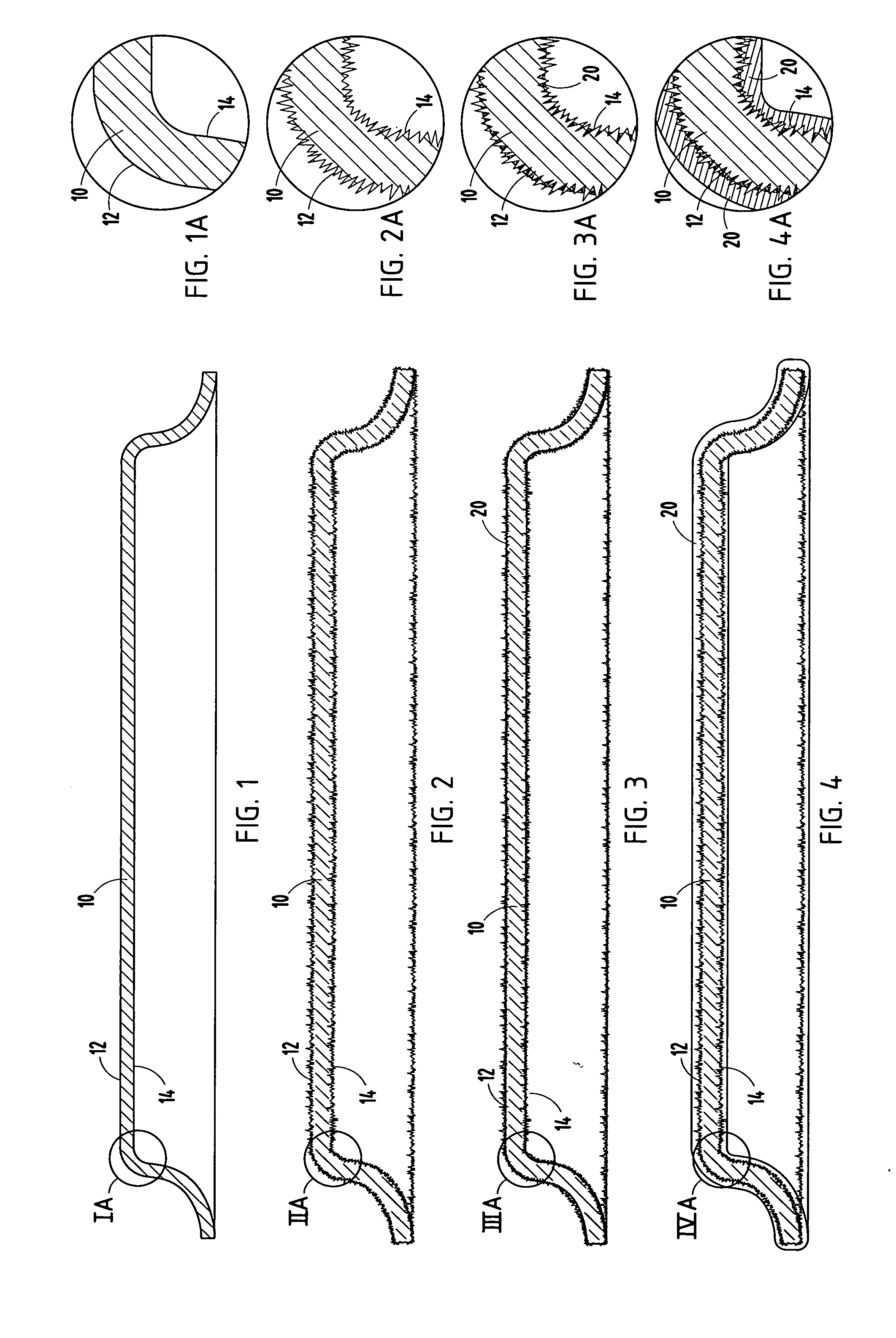
[0025]In accordance with certain aspects of the invention, there is provided a low-cost solution for developing thicker electrophoretic coatings on substrate surfaces while using conventional electrophoretic coating compositions. In certain other aspects, the invention provides a low-cost solution for providing electrically conductive electrophoretically coated surface while using conventional electrophoretic coating compositions. In certain aspects, the invention allows “dual coatings” on substrate surfaces to create a two or more layer or laminated electrophoretic coating system. More specifically, a part can be provided with multiple electrophoretic coating layers or lamina that can, for example, have different colors and / or different coating performance specifications. For example, a first electrophoretic coating could be rich in corrosion inhibitors, while a second electrophoretic coating layer could be an abrasion and / or ultraviolet-resistant layer.

[0026]As used herein, the te...


PUM

PropertyMeasurementUnit
heightaaaaaaaaaa
thicknessaaaaaaaaaa
thicknessaaaaaaaaaa

Abstract

A process for electrophoretically coating an electrically conductive substrate involves providing an electrically conductive substrate that is to be electrophoretically coated, pretreating the substrate surface to increase its asperity, and applying an electrophoretic coating composition to the treated substrate surface. The process allows the use of conventional electrophoretic coating compositions and / or processing equipment to achieve thicker coatings and / or to develop electrically conductive electrophoretically coated surfaces employing conventional electrophoretic coating compositions, processing parameters and / or equipment.

Description

FIELD OF THE INVENTION[0001]This invention pertains to coatings, and more particularly to improved electrophoretic coating techniques, thicker electrophoretic coatings and / or the development of electrophoretic coated surfaces that are electrically conductive.BACKGROUND OF THE INVENTION[0002]Electrophoretic coating processes are typically used to apply functional (e.g., corrosion resistant) and / or aesthetic coatings to metal surfaces. It is widely used in the manufacture of vehicle body parts, electrical switch gear, appliances, metal furniture and beverage containers. Electrophoretic coating processes are often more preferred than conventional coating techniques because the electrophoretic coating processes provide very uniform coating thicknesses, allow complex shaped objects to be easily coated, is more conductive to automation, is highly efficient in the utilization of the coating materials, and is more environmentally friendly and safer to use than most other coating technologie...

Claims


Application Information

Patent Timeline
Patent Type & Authority Applications(United States)
IPC IPC(8): B32B5/00C25D13/20
CPCC25D13/20Y10T428/266C25D13/22
Inventor STILLABOWER, MORRIS D.
Owner DELPHI TECH INC
Learn More