Reciprocating pneumatic piston gravity engine

Inactive Publication Date: 2010-03-11
CHAVEZ JULIO
View PDF7 Cites 7 Cited by
  • Summary
  • Abstract
  • Description
  • Claims
  • Application Information

AI Technical Summary

Benefits of technology

[0019]The present invention overcomes the limitations and disadvantages present in the art by providing an improved pneumatic reciprocating piston engine that uses a mixture of compressed air and water as the working fluid with a combination of gravity and spring force functioning to return the piston after completion of the power stroke. A working fluid, preferably comprising a source of compressed air, is in fluid communication with the bottom portion of a generally vertically disposed cylinder via an inlet valve biased to a normally closed position. A piston is configured for reciprocating motion within the cylinder and traverses between bottommost and topmost positions. The piston is configured to engage the inlet valve when at the bottommost position thereby actuating the valve for a limited period of time to an open position so as to allow the introduction of compressed air and initiating of the power stroke to drive the

Problems solved by technology

But no effective gasoline-powered engine was developed until 1859, when the French engineer J. J. Étienne Lenoir built a double-acting, spark-ignition engine that could be operated continuously.
A significant disadvantage present with the use of internal combustion engines that burn hydrocarbon fuel is the resulting pollution.
Use of a high pressure steam boiler, however, is considered undesirable due to complexity and the danger associated with high pressure steam.
Furthermore, the high temperature associated with s

Method used


Image

  • Reciprocating pneumatic piston gravity engine
  • Reciprocating pneumatic piston gravity engine
  • Reciprocating pneumatic piston gravity engine

Examples


Embodiment Construction

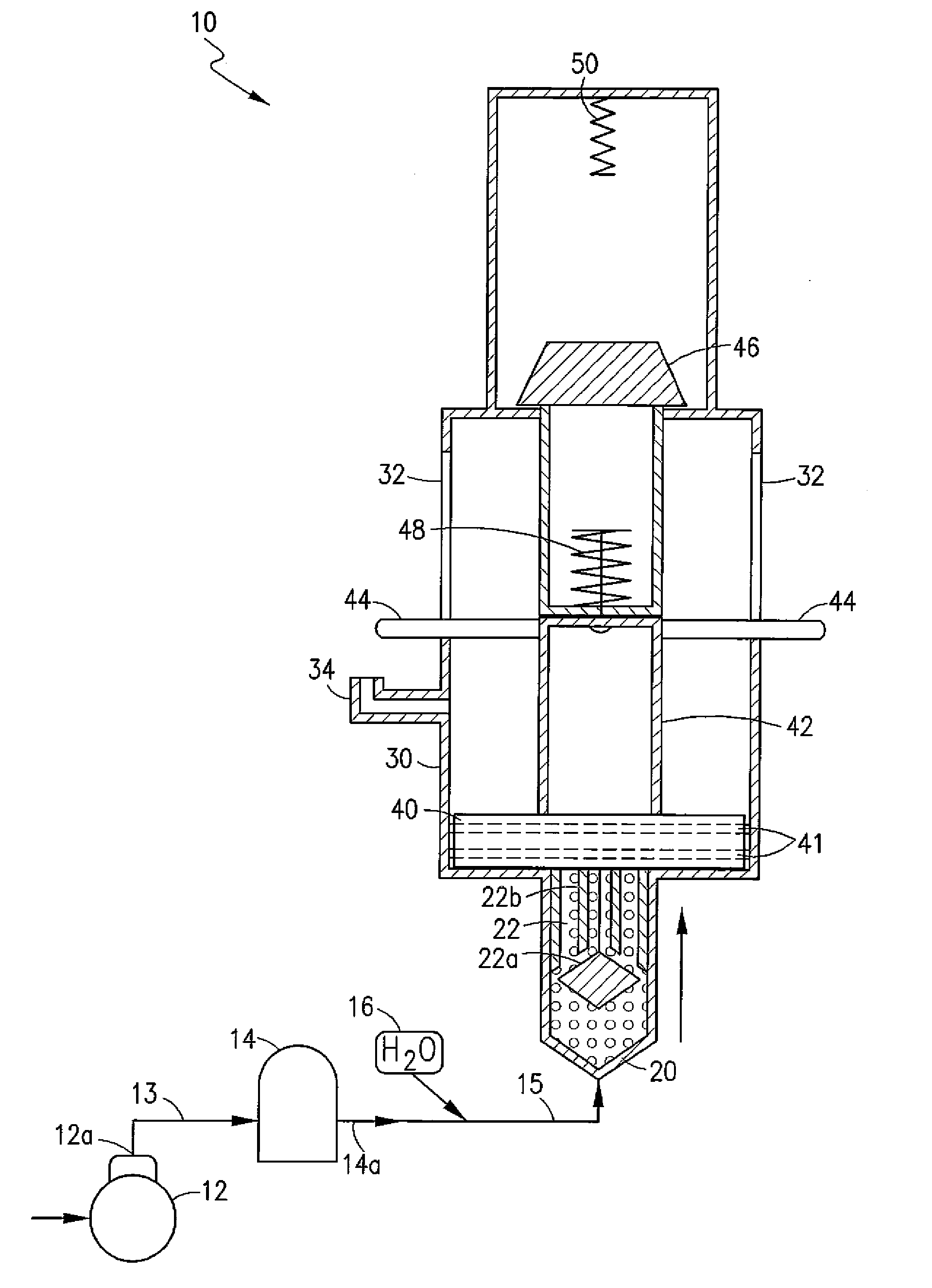
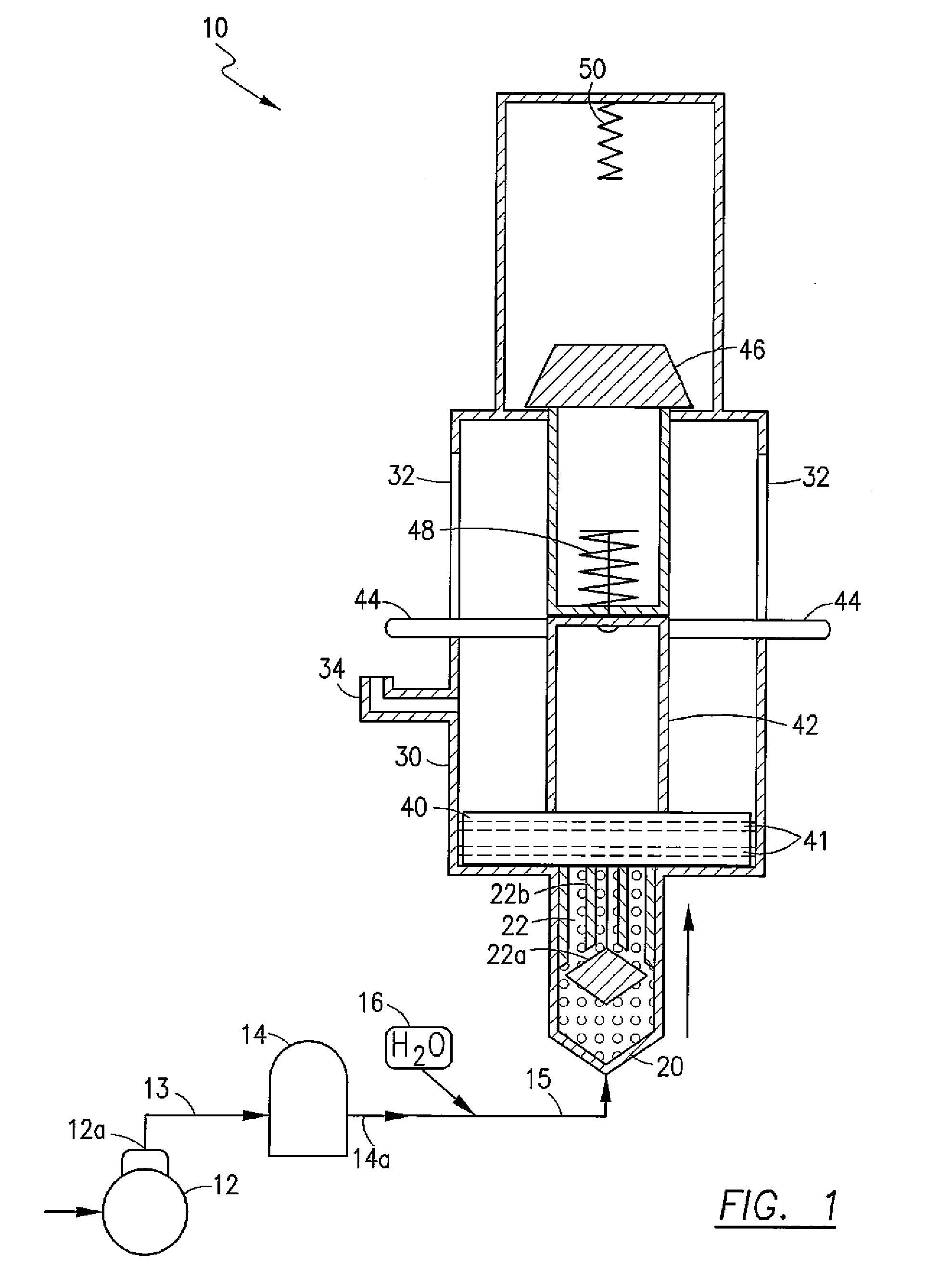
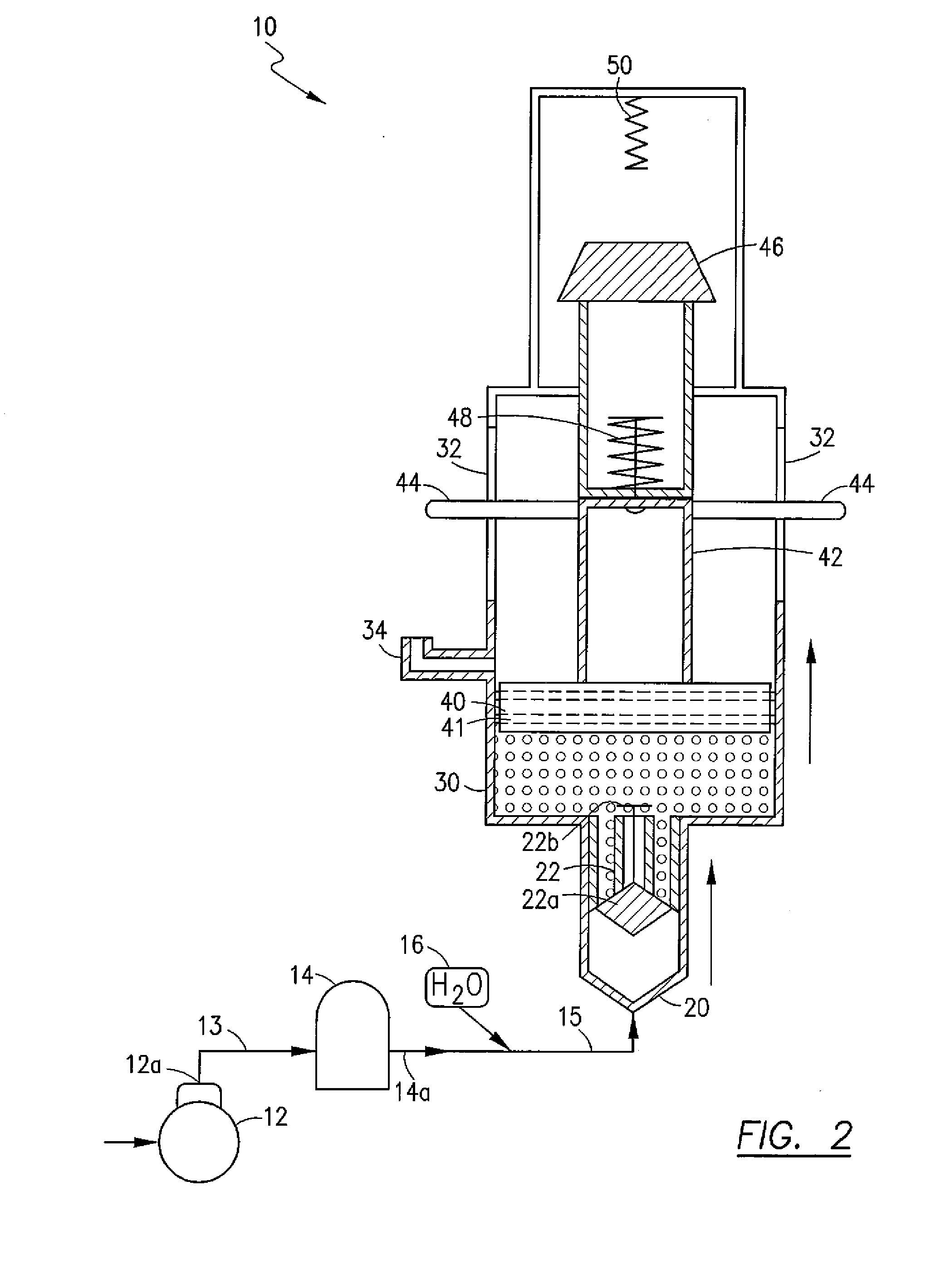
[0025]With reference now to the drawings, FIGS. 1-3 depict an improved pneumatic reciprocating piston engine, generally referenced as 10, in accordance with the present invention. Pneumatic engine 10 is powered by a mixture of compressed air and water. A compressor 12 has an outlet 12a in fluid communication with a pressure vessel 14 via a compressed gas line 13. Pressure vessel 14 has an outlet 14a in fluid communication with a cylinder intake, generally referenced as 20, via a compressed gas line 15. In a preferred embodiment, the compressed gas is air, however, the use of an alternate gas (such as Nitrogen) is considered within the scope of the present invention. A water source 16 is also in fluid communication with gas line 15 so as to provide a mixture of compressed air and water / water vapor to cylinder intake 20. Injecting a relatively small amount of water into the compressed air supply has been found to unexpectedly increase the work extracted from the compressed air. In add...


PUM


Abstract

A pneumatic reciprocating piston engine that uses a mixture of compressed air and water as the working fluid with a combination of gravity and spring force functioning to return the piston after completion of the power stroke is disclosed. A working fluid, preferably comprising a source of compressed air, is in fluid communication with the bottom portion of a generally vertically disposed cylinder via an inlet valve biased to a normally closed position. A piston is configured for reciprocating motion within the cylinder and traverses between bottommost and topmost positions. The piston is configured to engage the inlet valve when at the bottommost position thereby actuating the valve for a limited period of time to an open position so as to allow the introduction of compressed air and initiating of the power stroke to drive the piston upward. In a preferred embodiment, water is injected into the compressed air stream entering the cylinder to provide lubrication for the piston. The piston is drive upward by the working fluid until an uppermost stop is reached wherein the piston head has cleared an exhaust port formed in the cylinder thereby allowing the working fluid to escape. A mass is connected to the piston, in overhead relation, by a spring connection. When the piston reaches the uppermost stop, momentum causes the spring connected mass to continue upward thereby placing the spring in compression and maintaining the piston above the exhaust port so as to allow escape of the working fluid therethrough. Return of the mass downward, caused both by gravity and spring energy, causes the mass to engage the piston and return the piston to its bottommost position whereby another stroke is initiated. Power output may be transferred to any suitable system.

Description

CROSS REFERENCE TO RELATED APPLICATIONS[0001]N / ASTATEMENT REGARDING FEDERALLY SPONSORED RESEARCH OR DEVELOPMENT[0002]N / ACOPYRIGHT NOTICE[0003]A portion of the disclosure of this patent document contains material that is subject to copyright protection. The copyright owner has no objection to the facsimile reproduction by anyone of the patent document or patent disclosure as it appears in the Patent and Trademark Office patent file or records, but otherwise reserves all rights whatsoever.BACKGROUND OF THE INVENTION[0004]1. Field of the Invention[0005]The present invention relates generally to reciprocating piston engines, and more particularly to a pneumatic engine wherein a mixture of compressed air and water functions as the working fluid, with a combination of gravity and spring force functioning to return the piston after completion of the power stroke.[0006]2. Description of Related Art[0007]An internal combustion engine is one in which combustion of the fuel takes place in a co...

Claims


Application Information

Patent Timeline
IPC IPC(8): F16D31/02
CPCF03G7/10F03G7/00F03G7/0254
Inventor CHAVEZ, JULIO
Owner CHAVEZ JULIO
Why Eureka
Try Eureka