Method and System for Controlling Fuel to a Dual Stage Nozzle

a dual-stage nozzle and fuel control technology, which is applied in the ignition of turbine/propulsion engines, engine starters, lighting and heating apparatus, etc., can solve the problems of undesirable dynamics in the combustor, less than optimum atomization of fuel injected through the secondary stage, and less than optimum atomization at lower pressures

Inactive Publication Date: 2010-03-11
SIEMENS ENERGY INC
View PDF26 Cites 36 Cited by
  • Summary
  • Abstract
  • Description
  • Claims
  • Application Information

AI Technical Summary

Benefits of technology

[0009]In accordance with a further aspect of the invention, a dual stage nozzle fuel control system is provided for providing fuel to the combustor section of a gas turbine. The system includes a first nozzle stage comprising a plurality of primary nozzles, and a second nozzle stage comprising a plurality of secondary nozzles, each secondary nozzle being associated with a respective primary nozzle to form a nozzle pair. A plurality of primary fuel supply lines are provided, where one of the primary fuel supply lines is connected to each of the primary nozzles. A single stage fuel supply is connected to the primary fuel supply lines for supplying fuel to each of the primary fuel lines. The second nozzle stage includes a secondary fuel supply line extending from each of the primary fuel supply lines to one of the secondary nozzles, and a valve is located in each of the secondary fuel supply lines between a respective secondary nozzle and a primary fuel supply line. A sensor is provided for identifying a predetermined operating condition of the gas turbine, and a controller is provided for producing a signal in response to identifying the predetermined operating condition. The signal effects actuation of the valves whereby fuel from each of the primary fuel supply lines is conveyed through the primary and secondary nozzles of a respective nozzle pair.

Problems solved by technology

Since this pressure differential at the secondary stage is very low just above crack pressure, i.e., just after the valve opens, the atomization of fuel injected through the secondary stage is typically less than optimum at this operating point.
In addition to the above-mentioned problems, pressure actuated valves may become stuck in either an open or closed position, and may experience a condition called “chatter” where the valve opens and closes rapidly in the operating region of the crack points, which may produce undesirable dynamics in the combustor.
Line 4 illustrates the simplex nozzle flow where it is necessary to provide a high enough flow to meet base load flow requirements, resulting in less than optimum atomization at lower pressures.
It may be seen that this is not desirable in that nozzle “chatter” may be a problem when idling at FSNL.

Method used


Image

  • Method and System for Controlling Fuel to a Dual Stage Nozzle
  • Method and System for Controlling Fuel to a Dual Stage Nozzle
  • Method and System for Controlling Fuel to a Dual Stage Nozzle

Examples


Embodiment Construction

[0016]In the following detailed description of the preferred embodiment, reference is made to the accompanying drawings that form a part hereof, and in which is shown by way of illustration, and not by way of limitation, a specific preferred embodiment in which the invention may be practiced. It is to be understood that other embodiments may be utilized and that changes may be made without departing from the spirit and scope of the present invention.

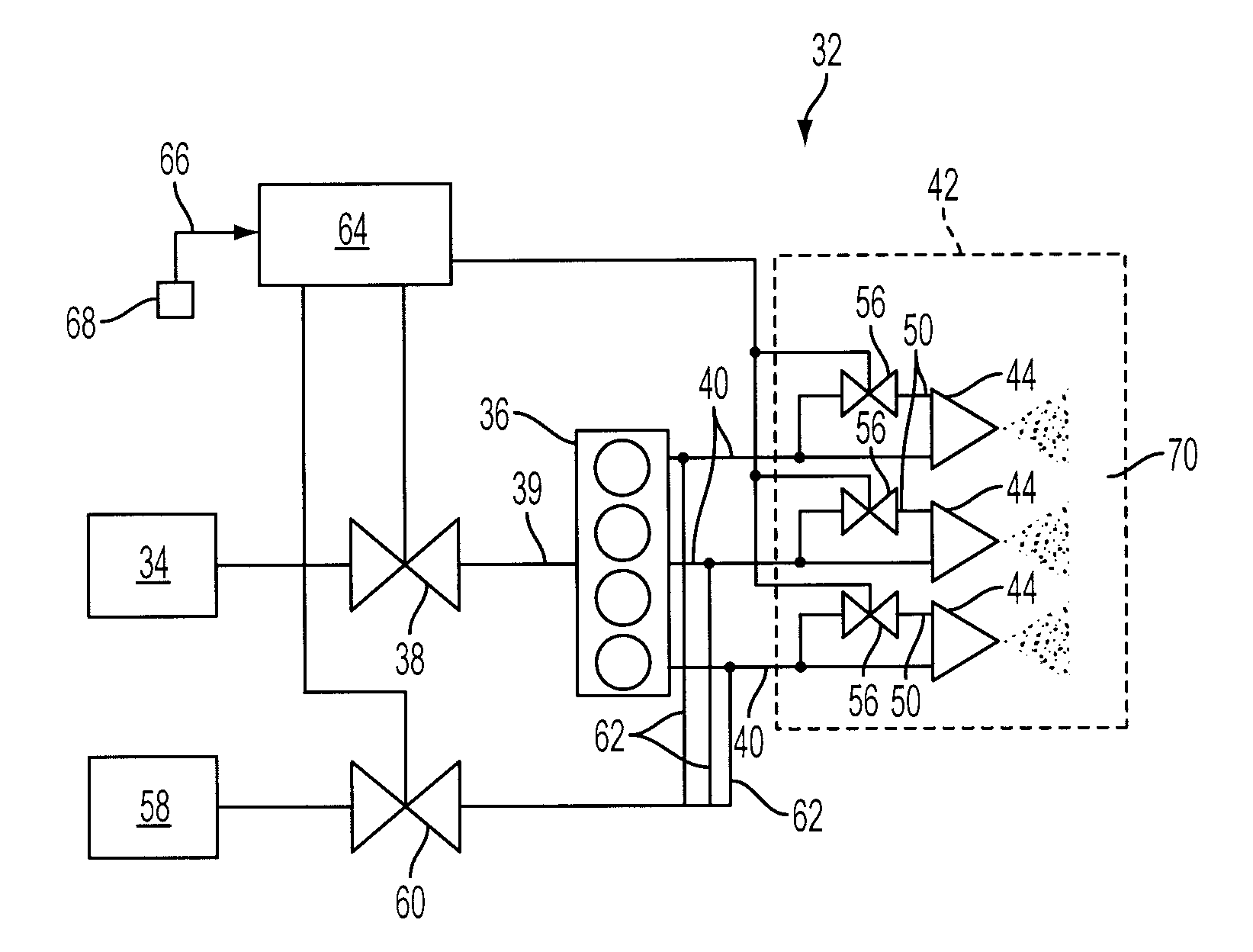
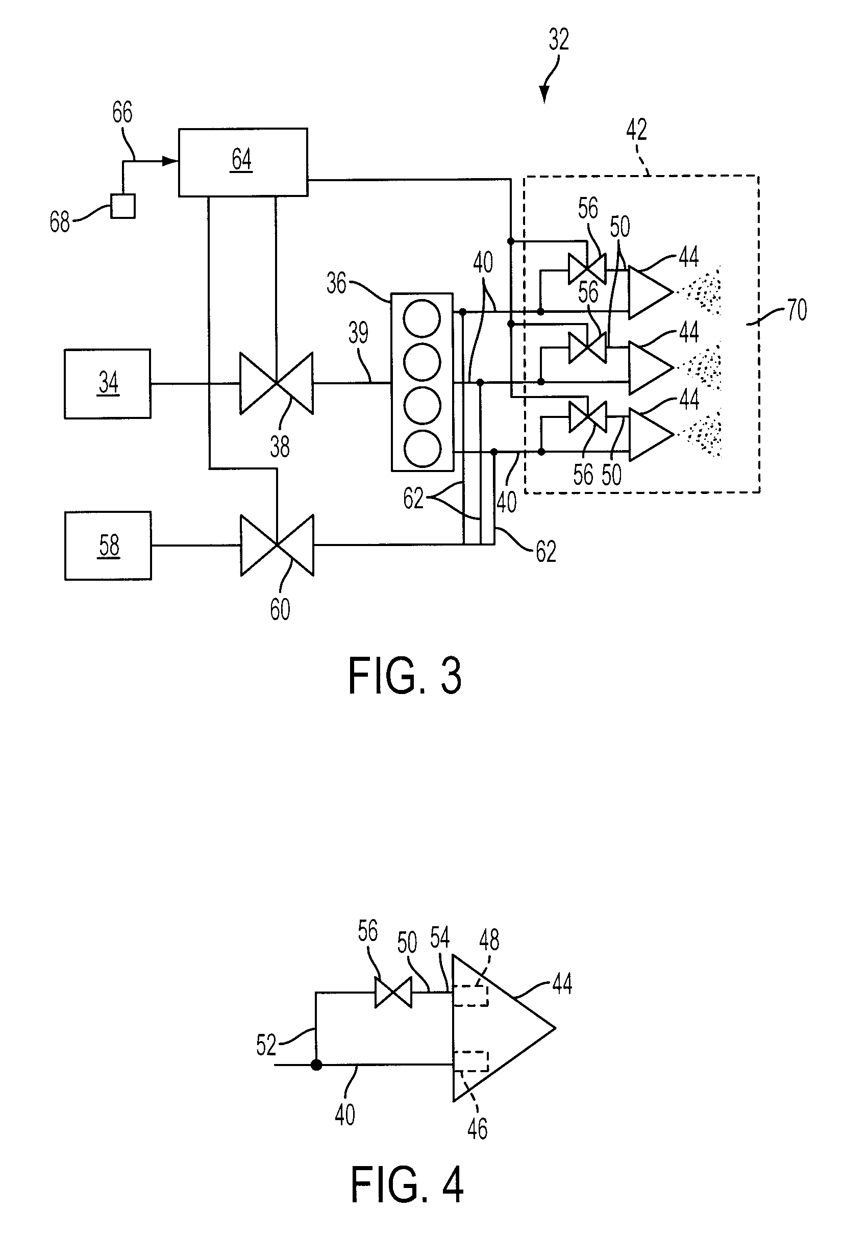
[0017]The present invention provides a method and system for controlling fuel to a dual stage nozzle. Referring to FIG. 3, a system 32 in accordance with the present invention is illustrated and includes a fuel supply 34 pumping a liquid fuel, e.g., fuel oil, to a flow divider 36 via a fuel control valve 38 and fuel line 39. The flow divider 36 splits the fuel flow to a plurality of primary fuel supply lines or primary legs 40 (only three shown), such that fuel flow is provided to each of the primary legs 40 at a substantially identical ...


PUM


Abstract

A method and system for controlling delivery of fuel to a dual stage nozzle in the combustor of a gas turbine. A liquid fuel is conveyed from a single stage fuel supply through a plurality of primary fuel supply lines to a first nozzle stage including a plurality of primary nozzles. A predetermined operating condition of the gas turbine is identified and a signal is produced in response to the identified operating condition. The signal effects actuation of valves located on secondary fuel supply lines extending from each of the primary fuel supply lines to supply fuel to respective secondary nozzles.

Description

FIELD OF THE INVENTION[0001]The present invention relates generally to the field of gas turbine engine and, more particularly, to a fuel control system for supplying fuel to a dual stage nozzle.BACKGROUND OF THE INVENTION[0002]Gas turbines are well known and used in various applications. As illustrated in FIG. 1, a typical gas turbine engine 10 includes a compressor 12 which draws in ambient air 14 and delivers compressed air 16 to a combustor 18. A fuel supply 20 delivers fuel 22 to the combustor 18 where it is combined with the compressed air to produce high temperature combustion gas 24. The combustion gas 24 is expanded through a turbine 26 to produce shaft horsepower for driving the compressor 12 and a load such as an electrical generator 28. The expanded gas 30 is either exhausted to the atmosphere directly, or in a combined cycle plant, may exhausted to atmosphere through a heat recovery steam generator (not shown).[0003]The fuel flow supplied to the combustor 18 from the fue...

Claims


Application Information

Patent Timeline
Patent Type & Authority Applications(United States)
IPC IPC(8): F02C7/22
CPCF23D11/38F23D2900/00015F23N1/002F23R3/343F23N2035/14F23N2035/28F23N2027/26F23N2227/26F23N2235/14F23N2235/28
Inventor RYAN, WILLIAM R.
Owner SIEMENS ENERGY INC
Why Eureka
Try Eureka