Transformer for reducing electromagnetic interference and power transform circuit applied therein

a transformer and electromagnetic interference technology, applied in the field of transformers, can solve the problems of lowering the operation efficiency of the transformer, still a problem to be solved, etc., and achieve the effect of reducing the emi

Active Publication Date: 2010-03-11
DELTA ELECTRONICS INC
View PDF4 Cites 9 Cited by
  • Summary
  • Abstract
  • Description
  • Claims
  • Application Information

AI Technical Summary

Benefits of technology

The present invention provides a transformer that reduces EMI (electromagnetic interference) and enhances the coupling rate between primary and secondary windings. The transformer includes a bobbin, magnetic core assembly, and primary and secondary windings. A shielded element is disposed between the primary and secondary windings to disconnect EMI transmission. The transformer further includes a second primary winding and a second shielded element to increase the electromagnetic coupling rate and reduce EMI dispersion. The power transform circuit includes a switch and a transformer for forming a minimum-route circuit to limit EMI dispersion. The technical effects of the present invention are reducing EMI and improving the efficiency of power transformation.

Problems solved by technology

Although the conventional transformer 1 certainly can achieve the effectiveness of voltage transform, there is still a problem need to be solved.
Furthermore, the generation of EMI will affect the electromagnetic coupling rate of the primary winding 13 and secondary winding and increase the leakage inductance of the transformer 1, resulting in lowering the operation efficiency of the transformer 1.

Method used


Image

  • Transformer for reducing electromagnetic interference and power transform circuit applied therein
  • Transformer for reducing electromagnetic interference and power transform circuit applied therein
  • Transformer for reducing electromagnetic interference and power transform circuit applied therein

Examples


Embodiment Construction

[0018]The present invention will now be described more specifically with reference to the following embodiments. It is to be noted that the following descriptions of preferred embodiments of this invention are presented herein for purpose of illustration and description only; it is not intended to be exhaustive or to be limited to the precise form disclosed.

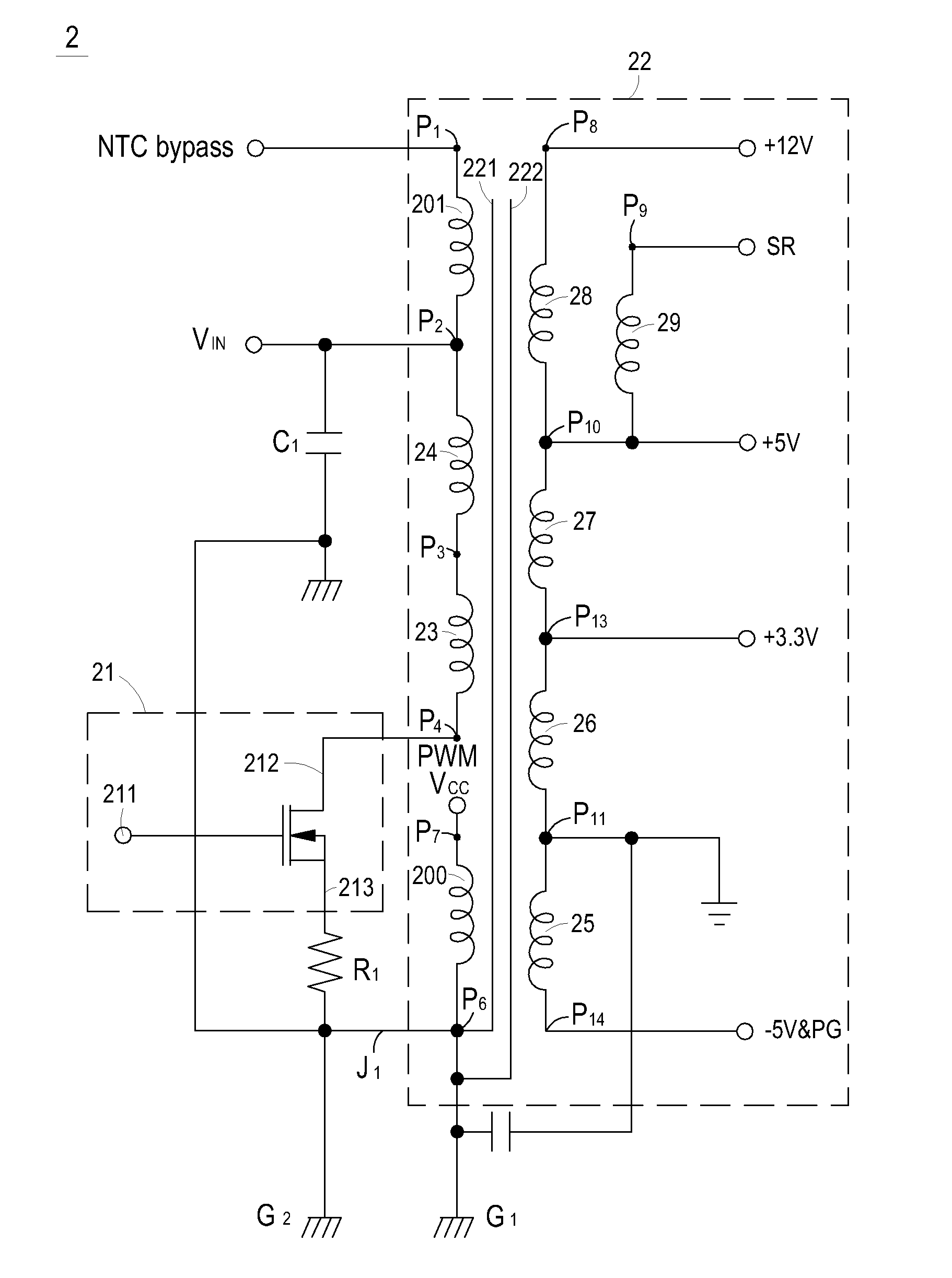
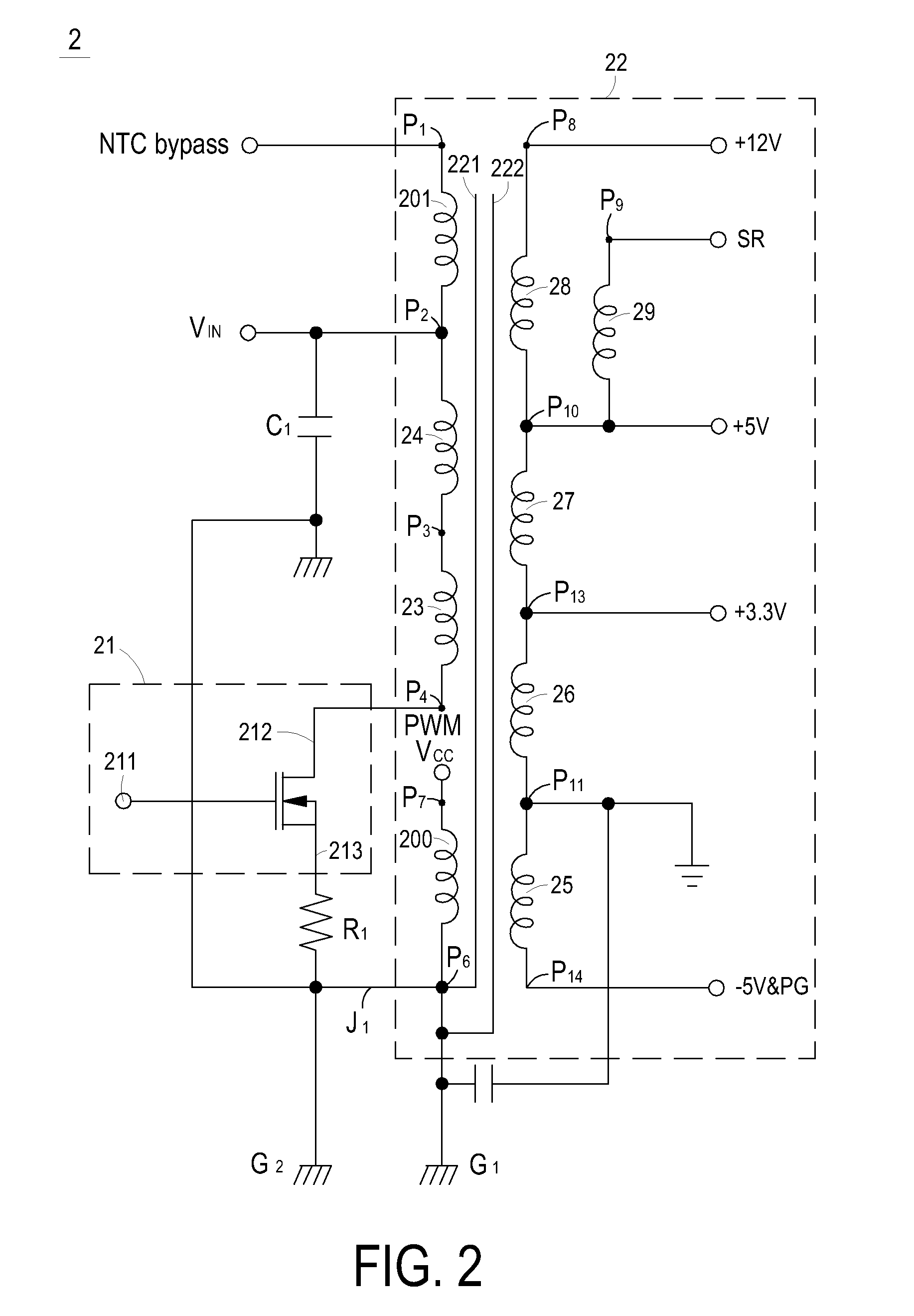
[0019]FIG. 2 is a circuit diagram illustrating a preferred embodiment of a power transform circuit according to the present invention. As shown in FIG. 2, a power transform circuit 2 includes a power input VIN, a switch 21, and a transformer 22. The transformer 22 is electrically connected to the power input VIN and the switch 21, respectively. The transformer 22 includes a primary winding, a secondary winding, a first shielded element 221, a second shielded element 222 and a plural of pins P1˜P4, P6˜P11 and P13˜P14.

[0020]In the preferred embodiment of FIG. 2, the primary winding can include a first primary winding 23 and a secon...


PUM

PropertyMeasurementUnit
electromagnetic interferenceaaaaaaaaaa
electromagnetic coupling rateaaaaaaaaaa
insulatingaaaaaaaaaa

Abstract

A transformer for reducing the electromagnetic interference (EMI) effect is disclosed. The transformer includes a bobbin; a magnetic core assembly partially sleeved by the bobbin; a first primary winding coiled around the bobbin; a secondary winding coiled on the first primary winding; and a first shielded element disposed between the first primary winding and the secondary winding for disconnecting the EMI transmission from the first primary winding to the secondary winding. The first primary winding includes a first winding portion and a second winding portion, and the first winding portion has larger EMI comparing to the second winding portion. The first winding portion of the first primary winding is adjacently disposed to the magnetic core assembly for shielding the EMI of the first primary winding by using the magnetic core assembly. The second winding portion is coiled on the first winding portion and adjacently disposed to the secondary winding for increasing the electromagnetic coupling rate of the first primary winding and the secondary winding. In addition, a power transform circuit applied in the transformer for reducing the EMI effect is also disclosed. The power transform circuit includes a switch, a power input for receiving a power signal; and a transformer electrically connected to the power input and the switch, for receiving and transforming the power signal.

Description

FIELD OF THE INVENTION[0001]The present invention relates to a transformer, and more particularly to a transformer for reducing electromagnetic interference (EMI). The present invention relates to a power transform circuit, and more particularly to a power transform circuit applied in a transformer for reducing EMI.BACKGROUND OF THE INVENTION[0002]Transformer is an electronic component for usually applying to various electronic apparatuses. Please refer to FIG. 1 which is a structure diagram illustrating a conventional transformer. As shown in FIG. 1, a conventional transformer 1 includes a magnetic core assembly 11, a bobbin 12, a primary winding 13 and a secondary winding (not shown in FIG. 1). The primary winding 13 and the secondary winding are coiled a winding region of the bobbin 12 by the sandwich-coiled type. That is, the primary winding 13 is separated to two portions covering the secondary winding, and the side-by-side adjacent region between the primary winding and the se...

Claims


Application Information

Patent Timeline
Patent Type & Authority Applications(United States)
IPC IPC(8): H01F27/36
CPCH01F27/36H01F27/2885H01F27/363
Inventor OUYANG, JR-HONGHSU, CHIH-HSUNLIN, JUI-LING
Owner DELTA ELECTRONICS INC
Why Eureka
Try Eureka