Free Air Magnetic Circuit and Speaker

Inactive Publication Date: 2010-03-11
NEDELCU EUGEN
View PDF0 Cites 3 Cited by
  • Summary
  • Abstract
  • Description
  • Claims
  • Application Information

AI Technical Summary

Benefits of technology

[0007]Embodiments of the present free air magnetic circuit and speaker provide for a driver that does not require a pole piece and does not utilize a backing behind the diaphragm. Accordingly, the speaker may be thinner and has reduced amounts of acoustic and ele

Problems solved by technology

This causes distortion of the sound and inhibits the free motion of the diaphragm 22.
This makes these speakers less conducive to use in environments in which thinner speakers would be more desirable, such as when mounting speakers in walls or in automobiles.
Another large problem with conventional drivers 10 is the high level of inductance due to the use of the ferrous metal pole piece 12.
In the speaker, t

Method used


Image

  • Free Air Magnetic Circuit and Speaker
  • Free Air Magnetic Circuit and Speaker
  • Free Air Magnetic Circuit and Speaker

Examples


Embodiment Construction

[0032]While the free air magnetic circuit and speaker is susceptible of various modifications and alternative constructions, certain illustrated embodiments thereof have been shown in the drawings and will be described below in detail. It should be understood, however, that there is no intention to limit the invention to the specific form disclosed, but, on the contrary, the invention is to cover all modifications, alternative constructions, and equivalents falling within the spirit and scope of the invention as defined in the claims.

[0033]In the following description and in the figures, like elements are identified with like reference numerals. The use of “or” indicates a non-exclusive alternative without limitation unless otherwise noted. The use of “including” means “including, but not limited to,” unless otherwise noted.

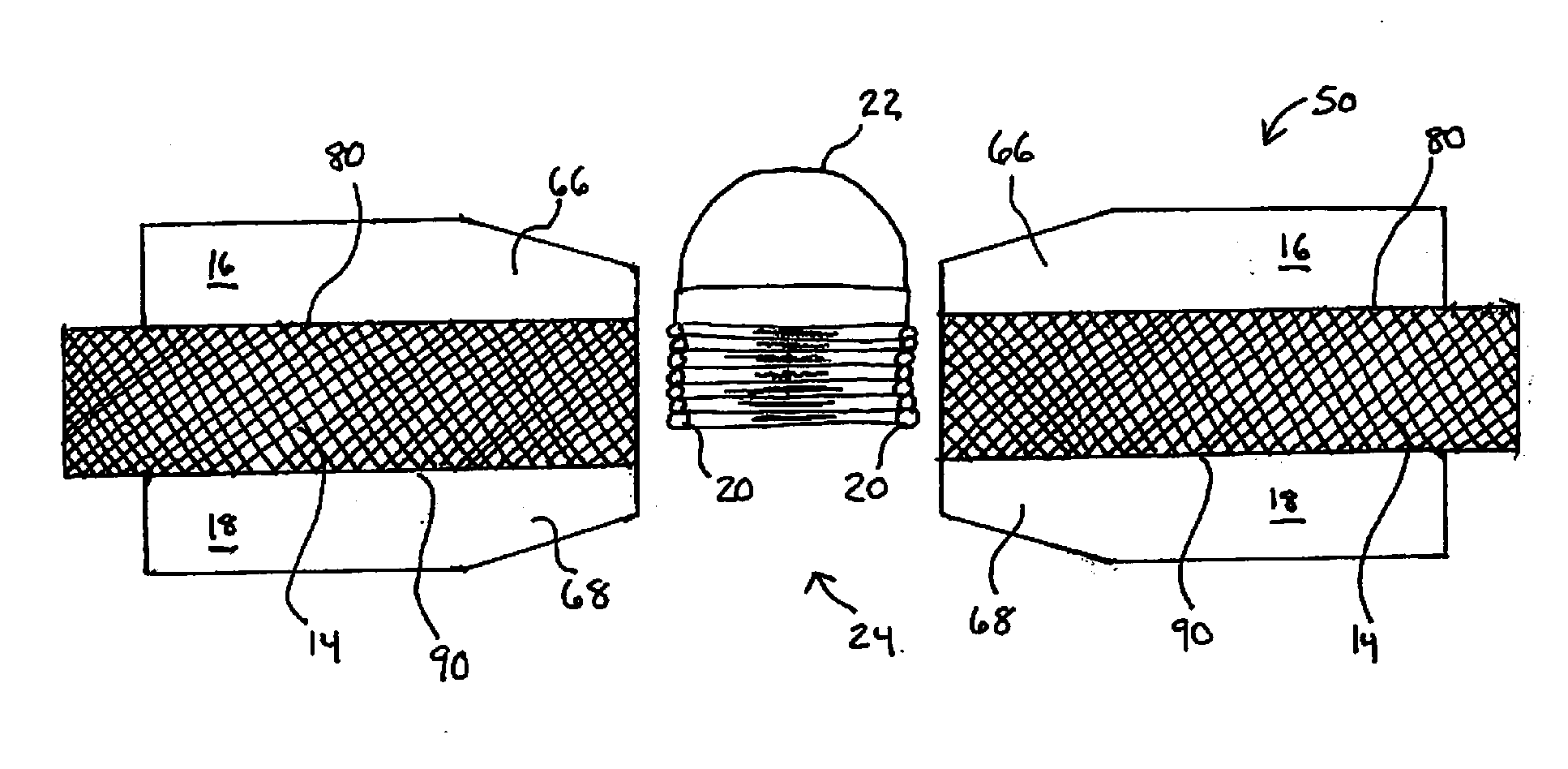
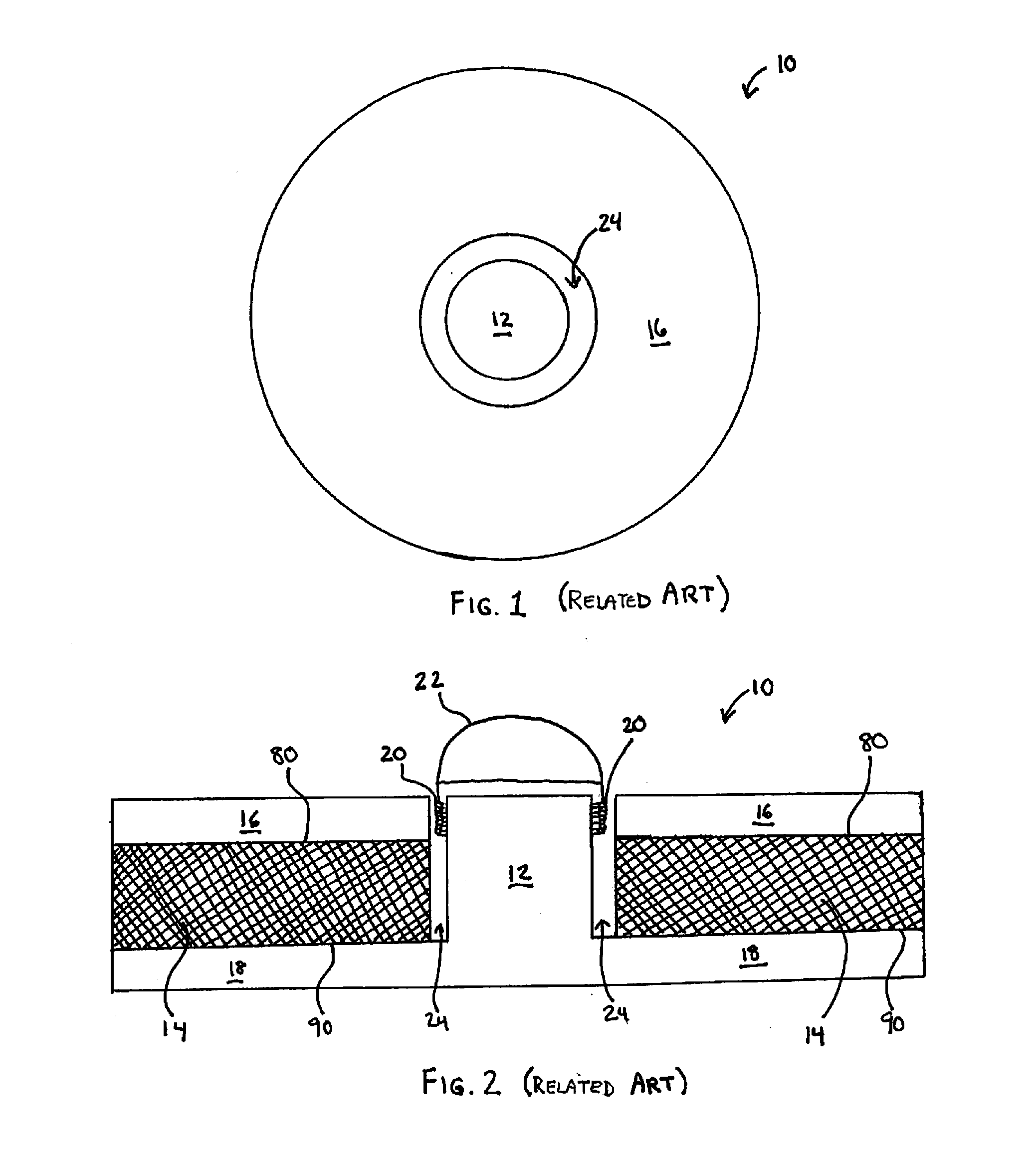
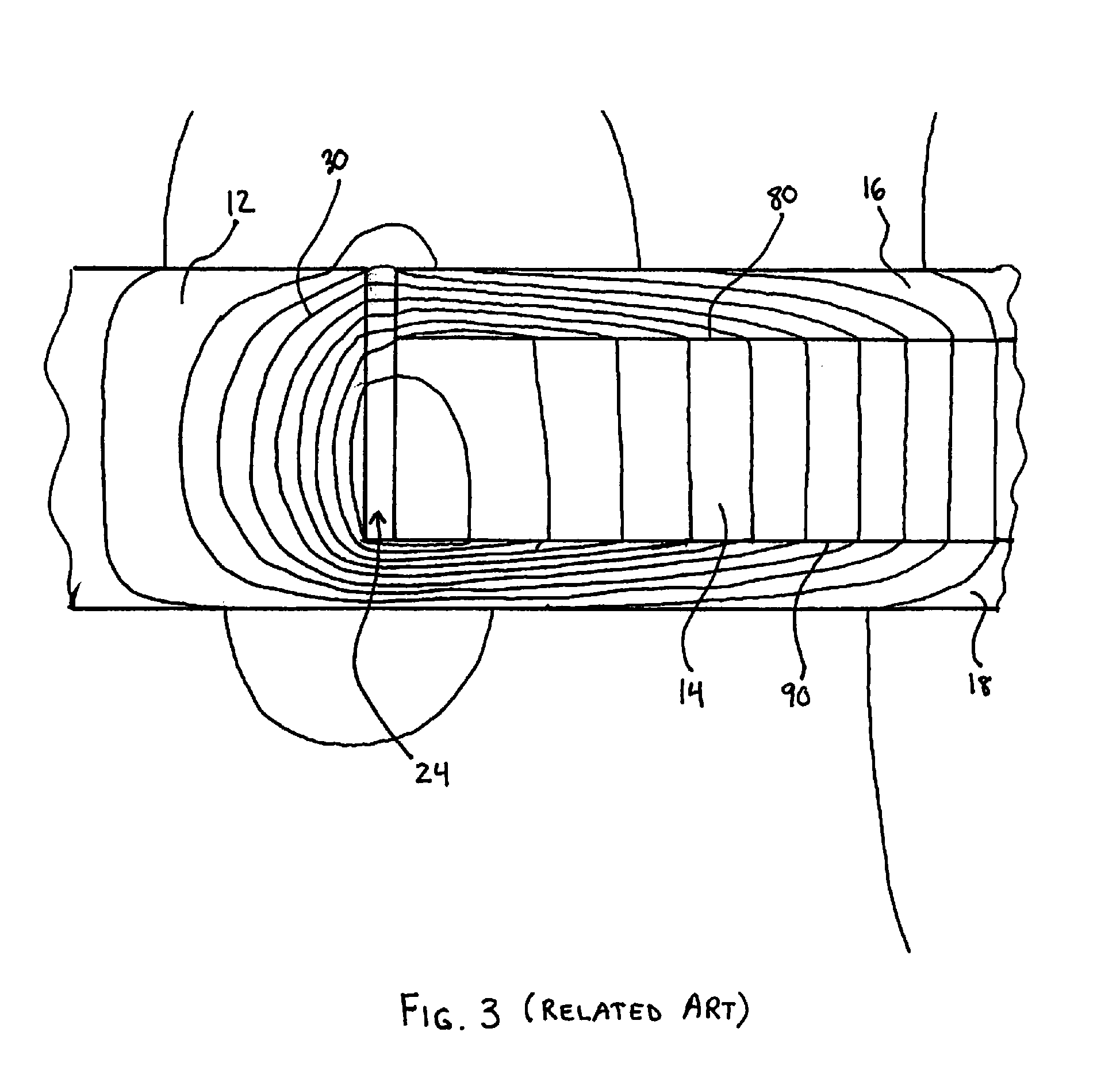
[0034]FIGS. 4 through 8 depict a first embodiment of the free air magnetic circuit 50 for inclusion in a speaker. Like a conventional magnetic circuit 10, the fr...


PUM


Abstract

Disclosed is a free air magnetic circuit and speaker in which no pole piece is used. A magnet layer is located between a top plate and a back plate with a gap defined essentially in the center thereof. Into the gap, a wire coil attached to a diaphragm may be inserted. A magnet flux passes between the top and back plates. In some embodiments, the interior edge of each of the metal plates tapers toward the gap, and the magnet layer extends past the peripheral edge of each of the metal plates so as to discourage magnetic flux between the metal layers at the peripheral edge.

Description

FIELD OF THE INVENTION[0001]The invention generally relates to speaker systems, and more particularly to a magnetic circuit for a speaker system in which no pole piece is included.BACKGROUND OF THE INVENTION[0002]Speakers convert electrical signals to sound via the use of drivers. A conventional driver 10 for a speaker is shown in FIGS. 1, 2, and 13. Common drivers 10 include a basket or frame to which is attached a lightweight diaphragm 22. Attached to the diaphragm 22 is a wire coil 20 wound round a pole piece 12 that sits at the center of a magnet ring 14 sandwiched between a top plate 16 and a back plate 18.[0003]The magnet ring 14 is usually polarized in the direction of the ring's thickness, e.g., with the north pole 80 adjacent the top plate 16 and the south pole 90 adjacent the back plate 18. As shown in FIG. 3, the magnet ring 14 generates a magnetic flux 30 that is dense in the gap 24 between the top of the pole piece 12 and the top plate 16. The wire coil 20 is located in...

Claims


Application Information

Patent Timeline
IPC IPC(8): H01F7/122
CPCH04R9/025H01F7/066
Inventor NEDELCU, EUGEN
Owner NEDELCU EUGEN
Why Eureka
Try Eureka