Smoke generating device

a smoke generating device and a technology for generating devices, which are applied in the field of cold smoke generating devices, can solve the problems of limiting the shelf life of the generator, requiring careful handling, and using or presenting highly reactive substances that are harmful and must be carefully handled, and achieves the effects of safe use, long shelf life, and simple manufacturing

Active Publication Date: 2006-10-26
NEXTTEQ
View PDF8 Cites 0 Cited by
  • Summary
  • Abstract
  • Description
  • Claims
  • Application Information

AI Technical Summary

Benefits of technology

[0011] It is an object of the present invention to provide a smoke generating tube which is simple to manufacture, safe to use and has a long shelf life.
[0012] Another objective of the invention is to apply contemporary materials and use their features to provide a completely sealed ready-to-use self-contained smoke generator that alleviates the need for a separate pump unit and mountable glass tube construction. The present invention incorporates the features of a pump and smoke generator into one unit which is easy hermetically assembled together.
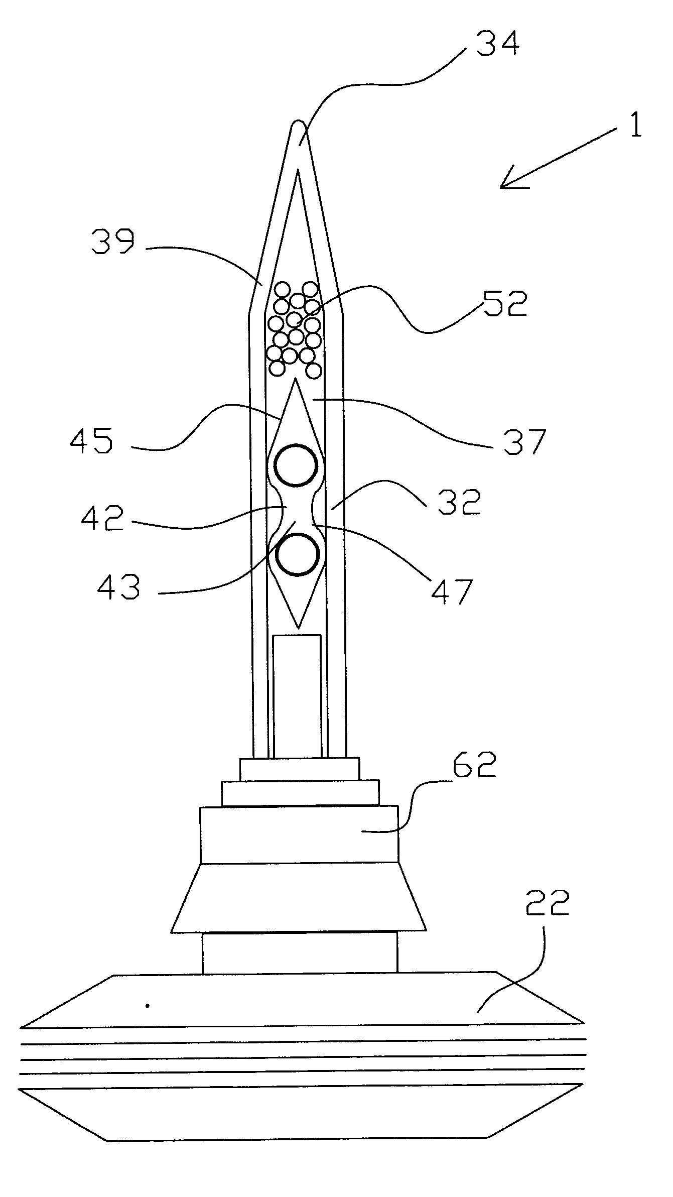
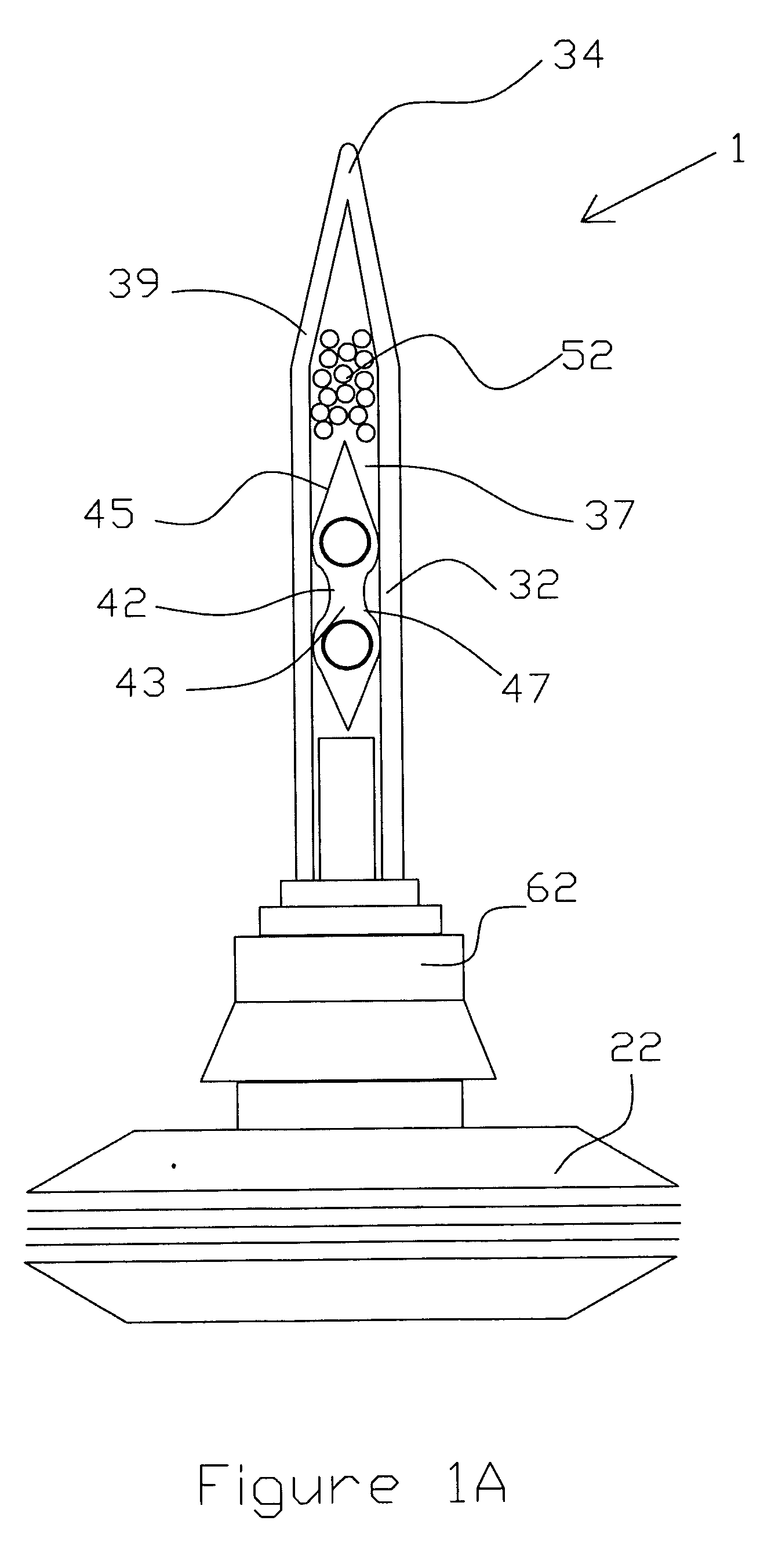
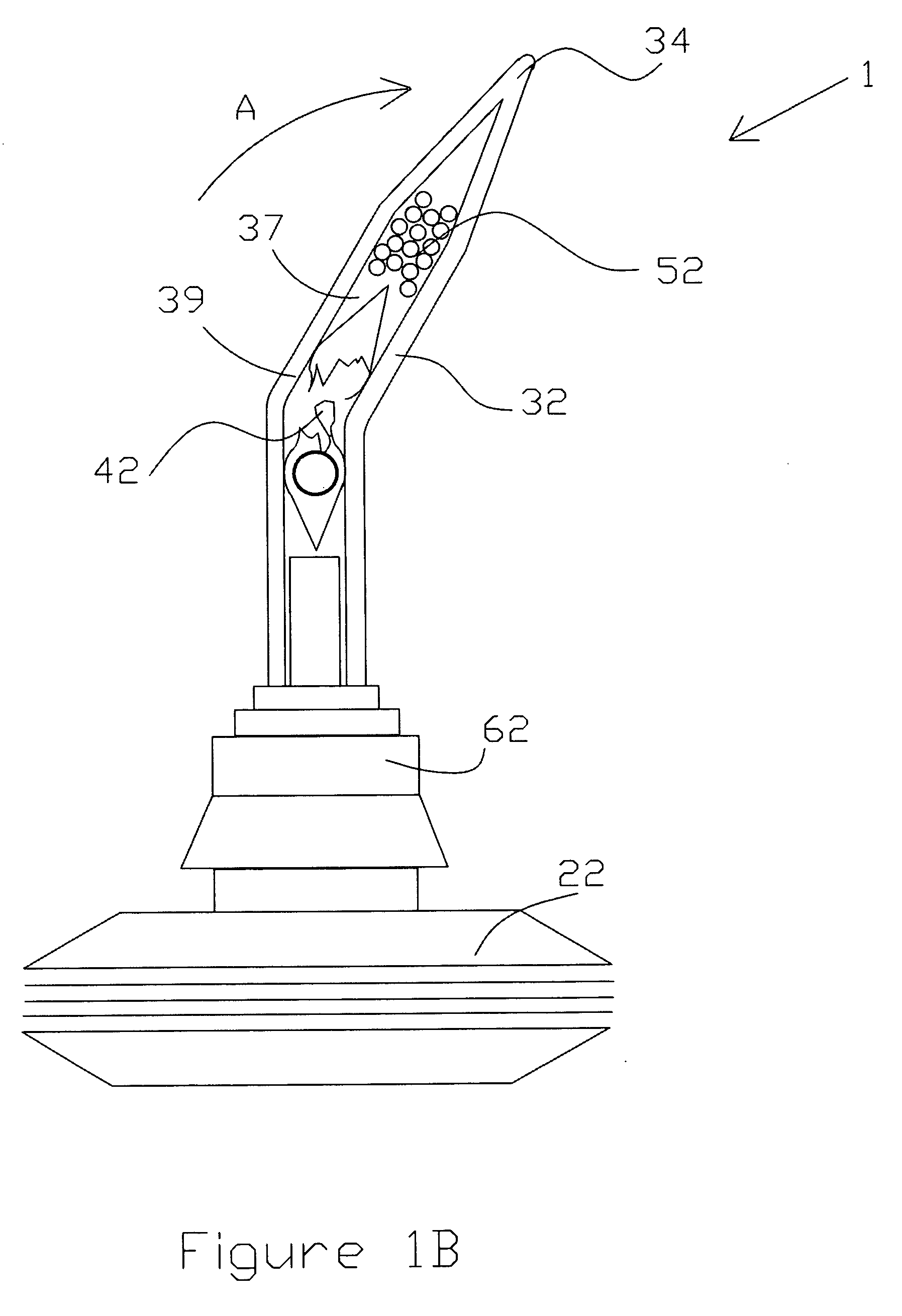
[0014] Each ampoule is filled with reagent or a plurality of reagents that react to produce a vapor or smoke. Each ampoule has at least one weakened region in the sidewall thereof to aid in breakage of the ampoule and release of a stored substance, such as a reagent. Typically the ampoule includes a region across the longitudinal axis which is mechanically less sound or rigid than the other areas of the ampoule structure. This region may be of smaller diameter than other regions of the sidewall comprising the ampoule, a mechanical scratch, notch or the like. The purpose of this mechanically weakened place is to allow easy breakage of the ampoule when the surrounded container is bent or twisted. The ampoules are immobilized and held in place within the interior of the flexible hollow plastic extension by means of at least one chemically-resistant plug. The plug may comprise felt, such as polypropylene or polyester felt, semi or fully sintered low or high porous plastic materials that exhibit low aerodynamic resistance characteristics.
[0016] When the collapsible container is squeezed, the air passes through the plugs, evaporates part of the reagent and mixes it within the chamber directly before the air is expelled from the removed end. Depending upon the type of reagents used, the vapors react together and / or with the air (preferably with normally present water content in the air) to generate an aerosol visible as smoke. Single compound reagents such as titanium tetrachloride and / or tin tetrachloride can be used to fill a single ampoule. Both of these reagents evaporate at over 100° C. (212° F.) and can be stored safely in ampoules. Their vapors when coming into contact with air, immediately forms aerosols exhibiting good visibility qualities. Less irritating fumes can be generated. by using two or more ampoules filed with acid and base reagents. As one skilled in the art will notice, the collapsible container serves as a portable source of air flow. Other sources, such as a hand pump, electric pump, blower or pressurized cylinder air supply, can be used provided the average air flow is within the same air flow range as with the original collapsible container.

Problems solved by technology

A major drawback of the known art is the use or presence of highly reactive substances that are harmful and must be carefully handled to prevent personal injury or property damage.
The process of manufacturing known smoke generators involves many difficult technological steps which result in more costly generators.
Another problem associated with the current smoke generators is the slow reaction between the active reagent and surrounding materials which limits the shelf life of the tubes.
Use of glass in the prior art devices presents a hazard to both the user and the generator itself.
Edges of broken glass are hazardous when the tube is used in close proximity with humans (such as in the air tight fitting tests for respirators).
The use of such glass tubes requires frequent changes of a rubber bulb used widely as a pump because glass particles tend to destroy or limit the life of the pump.
The whole construction is bulky and is unsafe.
The above mentioned problems and drawbacks apply to this device.
Moreover, it is very difficult to break the glass containers to activate the tube.

Method used


Image

  • Smoke generating device
  • Smoke generating device
  • Smoke generating device

Examples


Embodiment Construction

[0038] For one skilled in the art, the illustrated invention is self-explanatory and the features and advantages are self-explanatory as well. As seen on the drawings FIG. 1 A to E, the device 1 comprises a collapsible hollow container 22 is in fluid connection with one end of the flexible elongated extension 32 defined by a sidewall 39. The other end of the flexible extension 32 is sealed with tip 34 (or hermetical cap 38 shown on FIG. 3 and FIGS. 7-9). The flexible extension 32 includes an elongated chamber 37 for accommodating an ampoule 42. A plug 52 is disposed within chamber 37 between ampoule 42 and tip 34. A gas tight joint 62 connects the flexible extension 32 to the collapsible container 22.

[0039] In this embodiment, at least one ampoule 42 is filled with reagent. The ampoule includes a cavity 43 defined by ampoule sidewall 45. The ampoule sidewall 45 typically comprises crushable materials such as crystalline polystyrene, polymethylmetacrylate (acrylic), glass etc. In th...


PUM


Abstract

A cold smoke generating device includes an air source that may include a hollow flexible collapsible container having an expandable and compressible cavity for accepting air and air-borne reagent therein. The collapsible container is fluidly connected with a narrow flexible extension that includes an elongated cavity or chamber. Isolated and / or free reagents are disposed within the chamber of the narrow flexible extension. These reagents are capable of reacting with each other, with atmospheric air, or with other gases and fluids to generate a visible aerosol when expelled into the surrounding air.

Description

[0001] The present application is a continuation application of U.S. patent Ser. No. 10 / 926,517 filed on Aug. 25, 2004.[0002] The present invention did not receive any federal research and development funding. FIELD OF THE INVENTION [0003] The invention generally relates to a cold smoke generating device and more particularly to a device which comprises a hollow flexible collapsible container having an expandable and compressible cavity for accepting air and air-borne reagent therein. The collapsible container is fluidly connected with a narrow flexible extension that comprises an elongated cavity or chamber. Isolated and / or free reagents are disposed within said chamber of the narrow flexible extension. These reagents are capable of reacting with each other, with atmospheric air, or with other gases and fluids to generate a visible aerosol. This aerosol may be easily dispersed or expelled from the chamber by exerting a force or pressure onto an exterior of an expanded container cau...

Claims


Application Information

Patent Timeline
Patent Type & Authority Applications(United States)
IPC IPC(8): A63B53/00
CPCC06D3/00A01M13/00A62B27/00
Inventor KIROLLOS, KIROLLOS S.MIHAYLOV, GUEORGUI MILEV
Owner NEXTTEQ
Why Eureka
Try Eureka