Position detection system for detection object and position detection method for detection object

a technology of position detection and detection object, which is applied in the field of position detection system for detection objects and position detection method for detection objects, can solve the problems of recovery of detection objects, inability to perform calibration with the detection object remaining in the detection space, and inability to detect only the strength of ambient magnetic field, etc., and achieve the effect of enabling calibration

Inactive Publication Date: 2010-03-11
OLYMPUS CORP
View PDF11 Cites 86 Cited by
  • Summary
  • Abstract
  • Description
  • Claims
  • Application Information

AI Technical Summary

Benefits of technology

[0030]This allows the position-detection controlling unit to control the magnetic field strength, frequency, etc. of the position-detection magnetic field generated from the position-detection-magnetic-field generating section. The resonant circuit of the detection object can therefore reliably generate a resonant magnetic field that can be detected by the position-detection-magnetic-field detecting unit, as compared with the case where the position-detection controlling unit does not control the magnetic field strength etc. of the position-detection magnetic field.
[0031]The position detection system and method of the present invention for the detection object provide the advantage of enabling calibration without removing the detection object after the detection object is introduced into a detection space because the connecting or disconnecting of the external-signal switch of the resonant circuit is controlled to control the generation of the resonant magnetic field while the position-detection magnetic field is being applied to the resonant circuit.

Problems solved by technology

The above position detection method, however, has a problem in that, after the calibration, recalibration cannot be performed with the detection object remaining in the detection space.
Specifically, an error may occur in the calculated position of the detection object due to a difference between the magnetic field strength of the ambient magnetic field measured in the initial calibration and that of the ambient magnetic field used for position detection of the detection object, and recalibration may need to be performed to eliminate the above error.
In such a case, the above position detection method has a problem in that calibration for detecting only the strength of the ambient magnetic field cannot be performed with the detection object remaining in the detection space.
This can cause a problem in the recovery of the detection object because the detection object is recovered based on the positional information including the error preceding the recalibration.

Method used


Image

  • Position detection system for detection object and position detection method for detection object
  • Position detection system for detection object and position detection method for detection object
  • Position detection system for detection object and position detection method for detection object

Examples


first embodiment

[0062]A first embodiment according to a position detection system of the present invention will now be described with reference to FIGS. 1 to 4.

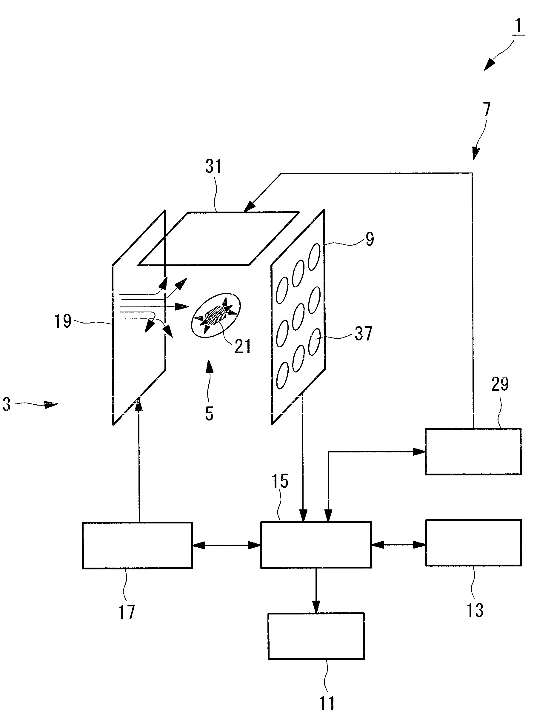
[0063]FIG. 1 is a schematic diagram outlining a position detection apparatus according to this embodiment.

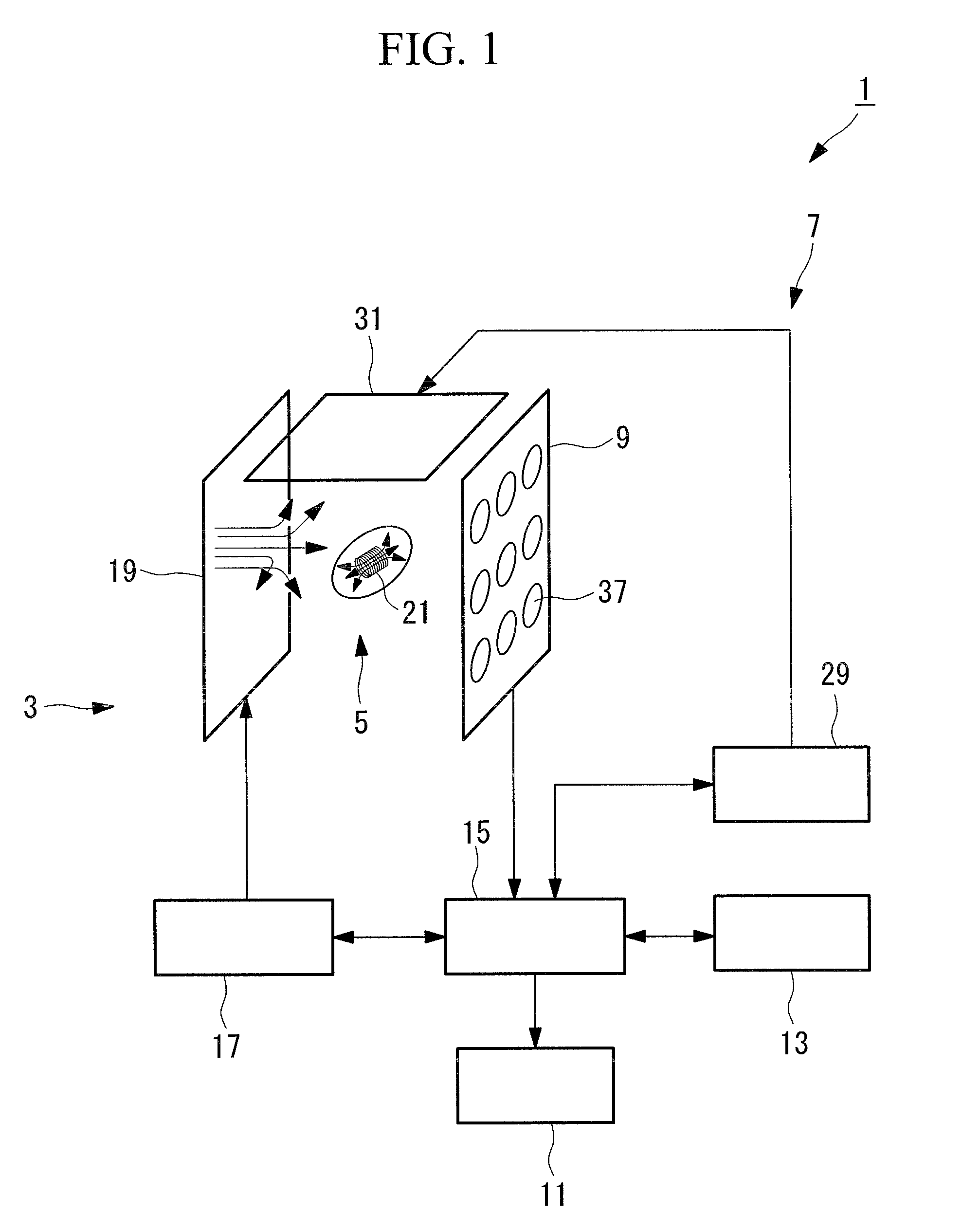
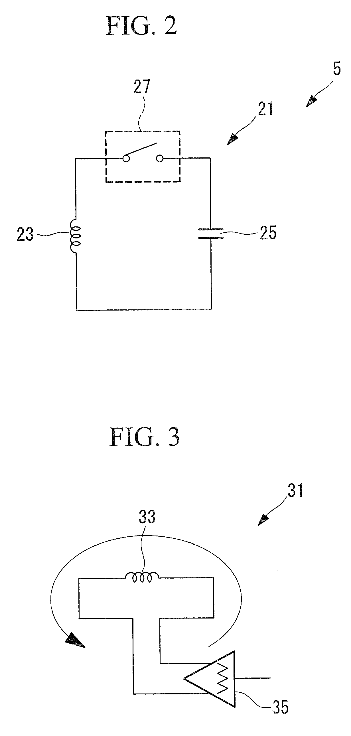
[0064]As shown in FIG. 1, a position detection system (position detection system for a detection object) 1 includes a magnetic-field generating unit (detection-magnetic-field generating unit) 3 that generates an alternating magnetic field for detecting the position of a detection object 5; the detection object 5, which generates a resonant magnetic field in response to the position-detection magnetic field; a switch-controlling unit 7 that controls the generation of the resonant magnetic field from the detection object 5; a position-detection-magnetic-field detecting unit 9 that detects the magnetic field strength of the position-detection magnetic field, or the magnetic field strength of the position-detection magnetic field and the res...

second embodiment

[0115]Next, a second embodiment of the present invention will be described with reference to FIGS. 5 to 10.

[0116]A position detection system of this embodiment has the same basic configuration as that of the first embodiment, but differs from that of the first embodiment in the method for controlling the resonant magnetic field. In this embodiment, therefore, only the method for controlling the resonant magnetic field will be described using FIGS. 5 to 10, and the other components etc. will not be described.

[0117]FIG. 5 is a schematic diagram outlining a position detection apparatus according to this embodiment.

[0118]As shown in FIG. 5, a position detection system (position detection system for a detection object) 101 includes a magnetic-field generating unit 3 that generates an alternating magnetic field for detecting the position of a detection object 105; the detection object 105, which generates a resonant magnetic field in response to the position-detection magnetic field; a po...

third embodiment

[0145]Next, a third embodiment of the present invention will be described with reference to FIGS. 11 and 12.

[0146]A position detection system of this embodiment has the same basic configuration as that of the second embodiment, but differs from that of the second embodiment in the method for distinguishing between calibration and position measurement. In this embodiment, therefore, only the method for distinguishing between calibration and position measurement will be described using FIGS. 11 and 12, and the other components etc. will not be described.

[0147]FIG. 11 is a block diagram outlining a position detection system according to this embodiment.

[0148]The same components as in the second embodiment are indicated by the same reference signs and will not be described.

[0149]As shown in FIG. 11, a position detection system (position detection system for a detection object) 201 includes a detection object 205 that is a capsule endoscope, an extracorporeal device 206 that processes an...


PUM


Abstract

A position detection system for a detection object and a position detection method for a detection object that enable calibration without removing a detection object after the detection object is introduced into a detection space are provided. Provided are a magnetic-field generating unit (3) that generates a position-detection magnetic field; a detection object (5) including a resonant circuit (21) that generates a resonant magnetic field and an external-signal switch that connects or disconnects the path of the resonant circuit (21); a switch-controlling unit (7) that controls connecting or disconnecting of the external-signal switch; a position-detection-magnetic-field detecting unit (9) that detects the magnetic field strength of at least one of the position-detection magnetic field and the resonant magnetic field; and a position-calculating unit (11) that calculates the position and orientation of the detection object (5) based on a detection signal from the position-detection-magnetic-field detecting unit (9).

Description

TECHNICAL FIELD [0001]The present invention relates to position detection systems for detection objects and position detection methods for detection objects.BACKGROUND ART [0002]A recently proposed position detection apparatus based on magnetic field detection creates a resonance state in an LC resonant circuit disposed in a detection object by supplying a magnetic field, acquires a magnetic field newly generated by the resonance through a plurality of magnetic field sensors, and detects the position and orientation of the detection object from the acquired information (see, for example, Patent Document 1 and Non-patent Document 1).[0003]In the technique described in Patent Document 1 above, the magnetic field strength detected by the sensors includes both the magnetic field strength of a magnetic field generated toward the LC resonant circuit and accidentally reaching the sensors (ambient magnetic field) and the magnetic field strength of a magnetic field generated from the LC reso...

Claims


Application Information

Patent Timeline
Patent Type & Authority Applications(United States)
IPC IPC(8): G08B21/00
CPCA61B5/06A61B5/073A61B5/062A61B1/041
Inventor KIMURA, ATSUSHIUCHIYAMA, AKIOSATO, RYOJICHIBA, ATSUSHI
Owner OLYMPUS CORP
Why Eureka
Try Eureka