Solar control film

a solar control and film technology, applied in the field of solar control films, can solve the problems of glass breakage, high cost, low production efficiency, etc., and achieve the effects of reducing investment cost, withstanding extremely high power levels, and high sputtering ra

Inactive Publication Date: 2010-03-11
SAINT GOBAIN PERFORMANCE PLASTICS CHAINEUX
View PDF8 Cites 20 Cited by
  • Summary
  • Abstract
  • Description
  • Claims
  • Application Information

AI Technical Summary

Benefits of technology

[0043]These rotatable targets are produced by plasma spraying of rutile powder in a reducing atmosphere (e.g. Ar / H2) on a stainless steel backing tube. The targets have enough electrical conductivity to be used as cathodes in a DC magnetron sputtering process and can withstand extremely high power levels. As a result, it is possible to achieve very high sputter deposition rates, at lower investment cost (both the deposition source itself and the power supply are considerably cheaper).

Problems solved by technology

However, by increasing the thickness of the metal layer, the visible light transmission will decrease to a level that is not acceptable.
However, this type of solar control films requires a slow and expensive process.
The high glazing temperature can lead to breakage of the glass in particular in architectural applications.

Method used


Image

  • Solar control film
  • Solar control film

Examples


Embodiment Construction

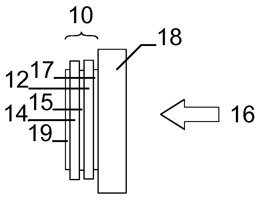
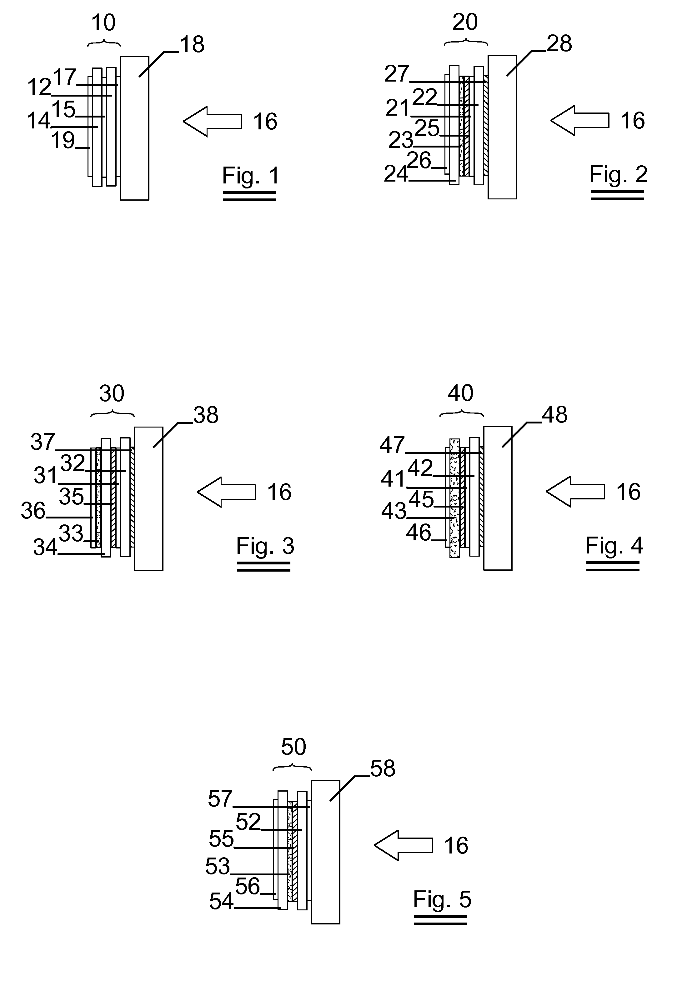
[0071]FIG. 1 shows a schematic representation of a solar control film 10 according to the present invention.

[0072]The solar control film 10 comprises an infrared reflecting layer 12 and an infrared absorbing layer 14. The infrared absorbing layer 12 is located further from the sun 16 than the infrared reflecting layer 12.

[0073]The infrared reflecting layer 12 and the infrared absorbing layer are laminated to each other by means of an adhesive 15.

[0074]The solar control film 10 is adhered to a glass substrate 18 by means of an adhesive 17.

[0075]Possibly, the solar control film comprises an additional layer 19 such as a hard coat layer or a scratch resistant layer.

[0076]FIG. 2 shows a detailed embodiment of a solar control film 20 according to the present invention.

[0077]The solar control film 20 comprises an infrared reflecting layer 21 and an infrared absorbing layer 23.

[0078]The infrared reflecting layer 21 comprises a silver or stabilized silver layer deposited on a first PET subs...


PUM

PropertyMeasurementUnit
thicknessaaaaaaaaaa
thicknessaaaaaaaaaa
diameteraaaaaaaaaa

Abstract

The invention relates to a solar control film comprising at least one infrared reflecting layer comprising a metal and at least one infrared absorbing layer comprising nanoparticles. The infrared absorbing layer is thereby located further from the sun than the infrared reflecting layer. By combining first reflection of the infrared energy and then absorption of the infrared energy, an optimum between reflection and absorption is obtained.

Description

FIELD OF THE INVENTION[0001]The invention relates to a solar control film.BACKGROUND OF THE INVENTION[0002]Flexible solar control films are known in the art to improve the energy transmission of a transparent glazing in buildings and vehicles.[0003]The most common function is to reduce solar heat load thereby improving comfort and reducing cooling load within a building or a vehicle.[0004]To reduce heat load, solar transmission is blocked in either the visible or the infrared portion of the solar spectrum.[0005]A number of different types of solar control films are known in the art.[0006]One type of solar control films known in the art comprises very thin layers of reflecting metal such as silver or aluminium deposited on a transparent substrate.[0007]Depending upon the metal and the thickness of the metal layer, the solar control film will have a certain visible light transmission (VLT) and a certain visible light reflection (VLR).[0008]To obtain an acceptable level of visible ligh...

Claims


Application Information

Patent Timeline
Patent Type & Authority Applications(United States)
IPC IPC(8): B32B5/16
CPCB32B17/10018B32B17/10174Y10T428/256G02B5/282G02B5/287B32B17/1055
Inventor DE MEYER, CHRISTYMOERKERKE, ROBRECHTPERSOONE, PETERSEGERS, ANNEKE
Owner SAINT GOBAIN PERFORMANCE PLASTICS CHAINEUX
Why Eureka
Try Eureka