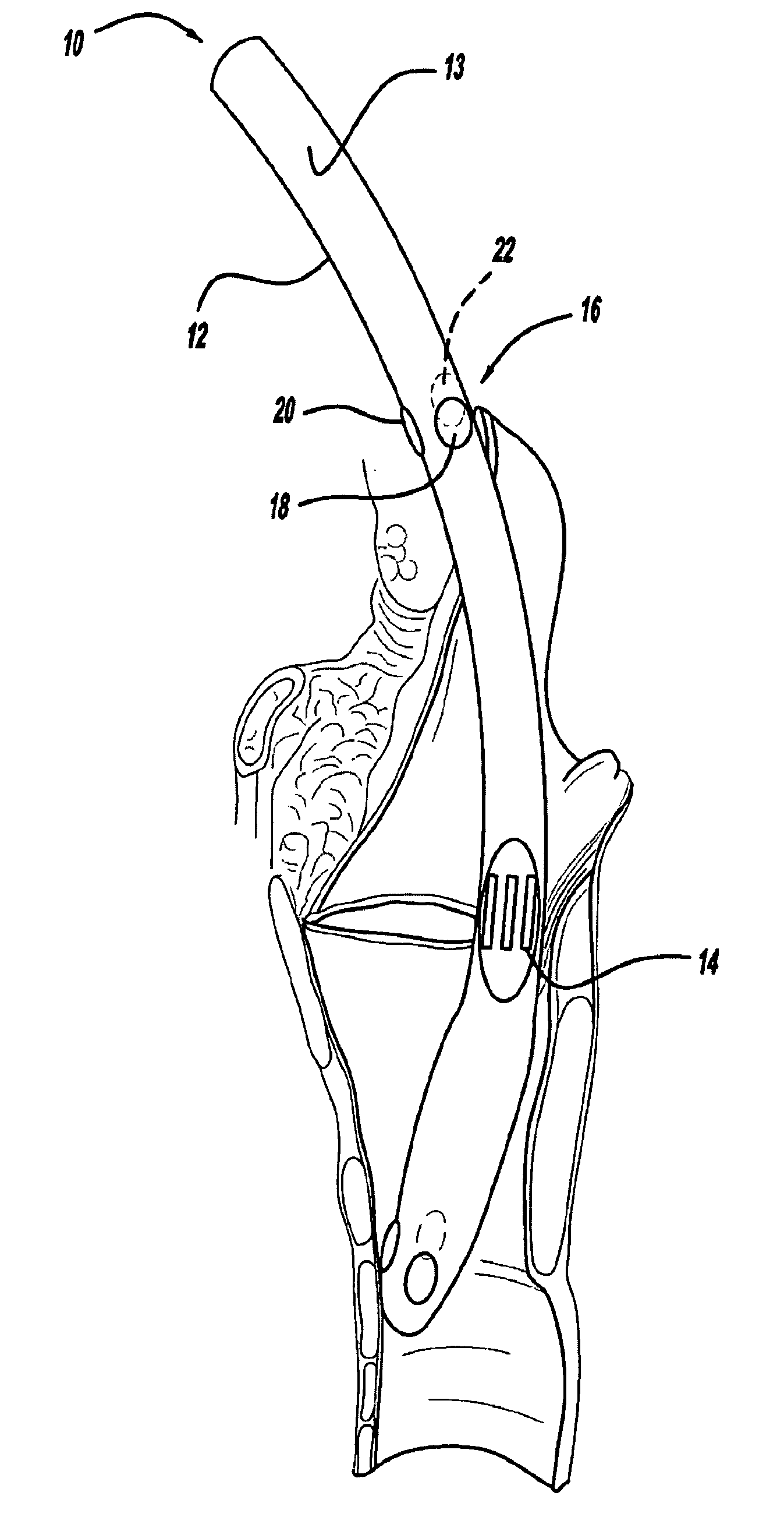
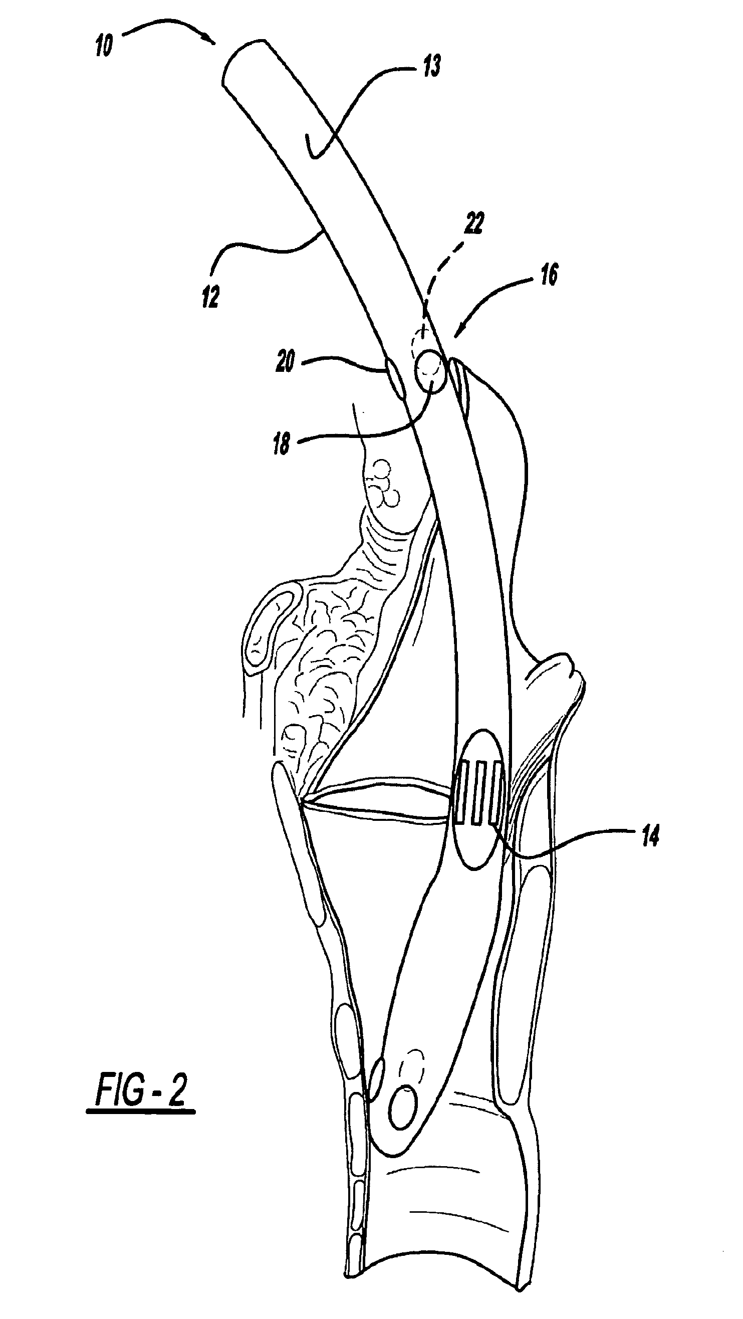
The small and difficult to find Recurrent Laryngeal Nerves may be inadvertently injured by even the most experienced surgeon.
Simply trying to identify the nerves can stretch or tear the nerve resulting in hoarseness, difficulty with speech, aspiration of food and liquids that can result in pneumonia, as well as life-threatening
airway obstruction.
ctrophysiologic RLN integrity does not always translate into clinical postoperative vocal fold mobility”. Rob
Current forms of RLN monitoring may also be inaccurate or ineffective due to anatomic, physiologic and technical causes.
The RLN, however, is a small, myelinated
branch of the
vagus nerve resulting in reduced sensitivity to electrical and, in particular, mechanical stimulation.
In contrast, monitoring of the small laryngeal muscles typically employs surface electrodes due to the practical difficulty and risks associated with placement of needle electrodes in the delicate laryngeal muscles.
However, this expediency carries significant disadvantages.
Detection of the EMG response is compromised not only by the inherent diminished amplitude of surface recording but due to difficulties in ensuring optimal contact between
electrode and vocal cord.
The ability to optimize the
Electrode-Vocal Cord (EVC) contact is limited by a number of factors.
Even if it is transiently checked once again after positioning the patient, loss of optimal EVC contact may go undetected.
Although this could be overcome by a flexible scope, the time and expense to add flexible fiberoptic
endoscopy following standard
intubation with a rigid laryngoscope makes it impractical if not prohibitive.
Second, there are numerous causes of electrode malposition.
It can be caused by too small of an ET, which would prevent adequate EVC contact.
One company, Medtronic (MDT) has attempted to minimize this by making tubes larger than normal, but this can make
intubation more difficult and may cause pressure trauma to the vocal cords.
The company's lack of “half size” tubes, exacerbates this problem.
Also, too deep or too shallow
insertion of the ET displaces the electrodes inferior or superior to the vocal cords.
Rotation of the ET skews the electrodes away from the vocal cords, which can result in a false
negative error.
The recent change to a more rigid reinforced tube (intended to make
intubation easier) exacerbates the problem as minor rotations of the tube at the mouth can result in rotations at the vocal cords.
This modification, however, increases the possibility of false positive error i.e. inadvertent electric stimulation of the inferior constrictor
muscle may be misinterpreted as true vocal cord movement because the increased
exposure of the tube's electrodes will pick up inferior constrictor
muscle activity.
The third problem is
drying at the EVC interface increases impedance which reduces detectability of the EMG response.
And fourth, too much
moisture from secretions or intentionally applied lubricating jelly may cause
shunting of the electrical response away from the electrodes.
Sub-optimal recoding parameters also create both false positive and false negative errors.
This technique suffers from two drawbacks: a) injury of the delicate vocal cord muscles by the penetrating needles, and b) difficulty in visualizing and accessing the cords.
For example,
puncturing the laryngeal muscles with needle electrodes can result in bleeding, scarring and infection.
Accurate placement of the needles through a long scope into tiny muscles is nonetheless a difficult endeavor.
This method has fewer drawbacks than the direct endoscopic approach but still requires considerable skill since the electrodes are placed blindly from outside to in, and the final electrode position cannot be visually confirmed.
Another problem is that simple needle electrodes may become displaced during
surgery.
While hook-shaped wire electrodes are more secure, they may cause more injury when they are later withdrawn.
These practical drawbacks of invasive
needle placement have led to the burgeoning use of non-invasive surface contacts.
The challenge here, as detailed above, is to avoid inadequate
Electrode-Vocal Cord (EVC) contact.
The ET tube-borne electrodes can be not only difficult to accurately place, but difficult to maintain in proper position.
Similar to the case of the ET tube electrode, the postcricoid placement requires considerable experience and skill to properly place the device—but rarely is such expertise available.
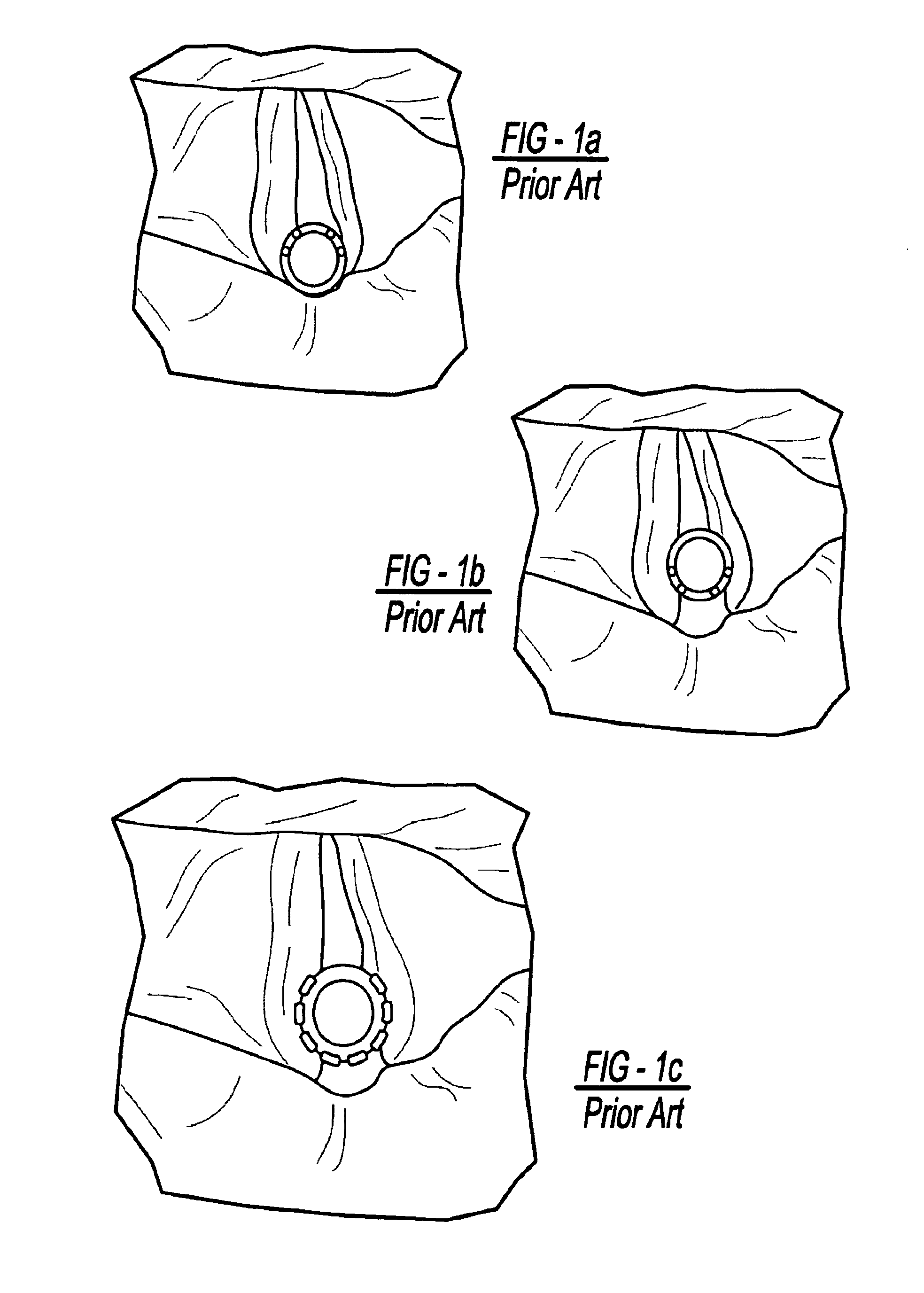
One problem with laryngeal surface electrodes is that the aperture created by the human
glottis is triangular whereas the ET tube is round.
This creates a fundamental mismatch between the surfaces.
Attempts to improve the
Electrode-Vocal Cord contact by simply increasing the outer
diameter of standard tubes to put more pressure of the electrode onto the vocal cords can lead to difficult and traumatic intubations as well as the possibility of pressure-induced vocal cord injury, particularly during prolonged operations such as removal of
skull base tumors.
A second problem is rotation of the ET tube around its
long axis which displaces the electrodes away from the cords.
A third problem is the depth that the ET tube is inserted.
Similar to rotation, a ET tube placed too shallow or too deep within the
throat will result in poor
electrode contact with the cords.
A ET tube inserted too deep may not only miss the cords but may pick up activity from other lower muscles in the neck (pharyngeal constrictors).
Such “false positive errors’ can lead to considerable anatomic disorientation of the surgeon.
Thus if the patient's head is subsequently moved after intubation, as typically occurs with surgical positioning, even a properly placed ET tube may become dislocated.

