All-digital line-of-sight (LOS) processor architecture
a processor and all-digital technology, applied in direction finders, instruments, measurement devices, etc., can solve the problems of the degree of alignment error between peak detection and delayed analog signals, and achieve the effect of improving pulse detection, los calculation, and reducing size, weight and power
Active Publication Date: 2010-03-18
RAYTHEON CO
View PDF4 Cites 18 Cited by
- Summary
- Abstract
- Description
- Claims
- Application Information
AI Technical Summary
Benefits of technology
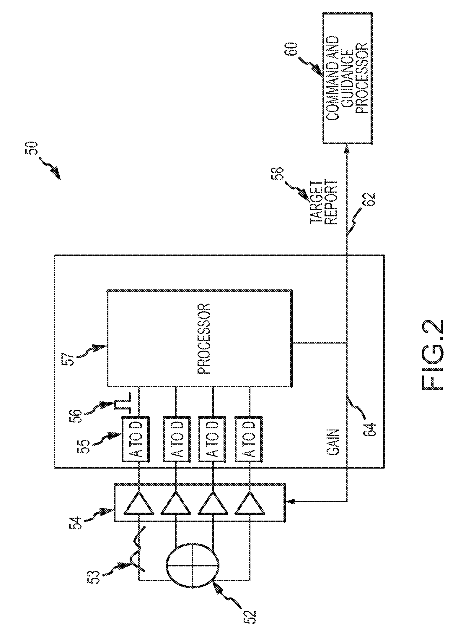
[0007]The present invention provides an all-digital LOS processor architecture with improved pulse detection and LOS calculation performance at reduced size, weight and power that provides a platform for enhanced techniques for sensitive pulse detection over a wide field-of-view, adaptive pulse detection, LOS processing and counter measures.
[0008]In a first embodiment, the all-digital LOS processor includes a plurality of A / D converters for converting analog signals from a multi-channel detector into a plurality of digital signals on respective individual channels. A digital summer sums all the digital signals to produce a digital signal on a primary sum channel. The architecture is expandable to sum different subsets of less than all the individual digital signals to produce digital signals on respective secondary sum channels. The secondary sum channels fill the gap between the field of view (FOV) of the individual channels and the primary sum channel.
Problems solved by technology
Errors in detection or LOS processing can cause mission failure.
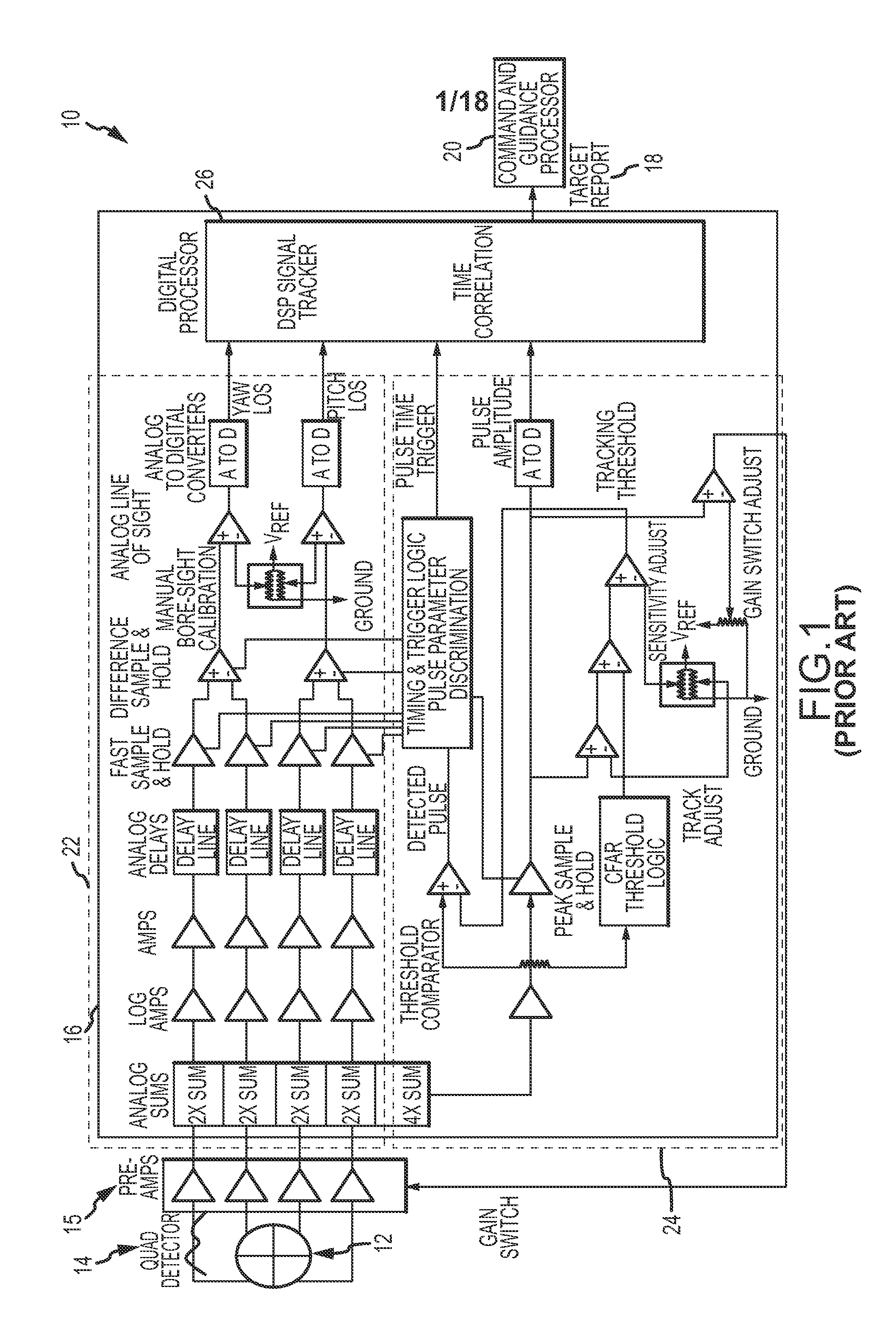
Ideally, the analog signals are sampled at the peak but there is some degree of alignment error between peak detection and the delayed analog signals.
Method used
View moreImage
Smart ImageViewing Examples
Examples
Login to View More PUM
 Abstract
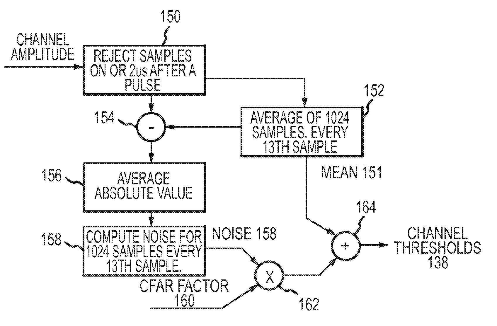
An all-digital line-of-sight (LOS) process architecture addresses the size, weight, power and performance constraints of a receiver for use in semi-active or active pulsed electromagnetic (EM) targeting systems. The all-digital architecture provides a platform for enhanced techniques for sensitive pulse detection over a wide field-of-view, adaptive pulse detection, LOS processing and counter measures.
Description
BACKGROUND OF THE INVENTION[0001]1. Field of the Invention[0002]This invention relates to a line-of-sight (LOS) processor architecture for a receiver for use in semi-active or active pulsed electromagnetic (EM) targeting systems, and more particularly to an all-digital architecture that addresses the size, weight and power constraints of typical applications and provides a platform for enhanced techniques for sensitive pulse detection over a wide field-of-view, adaptive pulse detection, LOS processing and counter measures.[0003]2. Description of the Related Art[0004]Certain aircraft, missiles and smart projectiles include a receiver that allows the platform to receive and process EM pulses, typically in the near IR, transmitted by a known source and returned off of a target. The receiver may be fixed to look along the line-of-sight (LOS) of the platform or gimbaled to look along a receiver LOS relative to the platform LOS. If the source is remotely located the system is referred to ...
Claims
Login to View More Application Information
Patent Timeline
 IPC IPC(8): G01S17/02
CPCG01S3/30G01S3/32G01S13/4445G01S13/42G01S3/325F41G7/226F41G7/2293
Inventor TYREE, ANTHONY K.SNYDER, MICHAEL C.HOUSER, DONALD R.SCHMITT, WILLIAM J.SCHALLER, ROBERT J.
Owner RAYTHEON CO
Features
- R&D
- Intellectual Property
- Life Sciences
- Materials
- Tech Scout
- Unparalleled Data Quality
- Higher Quality Content
- 60% Fewer Hallucinations
Learn More Browse by: Latest US Patents, China's latest patents, Technical Efficacy Thesaurus, Application Domain, Technology Topic, Popular Technical Reports.
© 2025 PatSnap. All rights reserved.Legal|Privacy policy|Modern Slavery Act Transparency Statement|Sitemap|About US| Contact US: help@patsnap.com


