Light source set and back light module

a technology of light source set and backlight module, which is applied in the direction of lighting and heating equipment, instruments, transportation and packaging, etc., can solve the problems of uneven light source distribution, large size, and radiation problem of crt, and achieve the effect of improving the distribution density of leds

Inactive Publication Date: 2010-03-18
CHUNGHWA PICTURE TUBES LTD
View PDF5 Cites 16 Cited by
  • Summary
  • Abstract
  • Description
  • Claims
  • Application Information

AI Technical Summary

Benefits of technology

[0008]The present invention is directed to a light source set, which can improve a distribution density of LEDs.
[0018]In the present invention, the point light sources are disposed on two opposite circuit boards, so that the disposing density of the point light sources can be increased according to different design requirements without being limited by the circuit layout spaces within the light source set. In other words, the point light sources with high disposing density can be applied to the light source set and the backlight module of the present invention according to different design requirements, so as to achieve a better light-emitting effect. Moreover, in the light source set and the backlight module of the present invention, the point light sources are not mutually overlapped, which avails thinning the light source set and the backlight module.

Problems solved by technology

Though a conventional cathode ray tube (CRT) display still has its own advantages, it has an excessive size and occupies a relatively great space due to an internal electron beam gun structure thereof, and the CRT also has a radiation problem during displaying.
However, the point-distributed LED light sources may have a problem of uneven light source distribution.
Moreover, suitable circuit layout spaces have to be maintained among the LEDs, so that a distribution density thereof cannot be improved, and therefore light source brightness cannot be increased according to utilization requirements.

Method used


Image

  • Light source set and back light module
  • Light source set and back light module
  • Light source set and back light module

Examples


Embodiment Construction

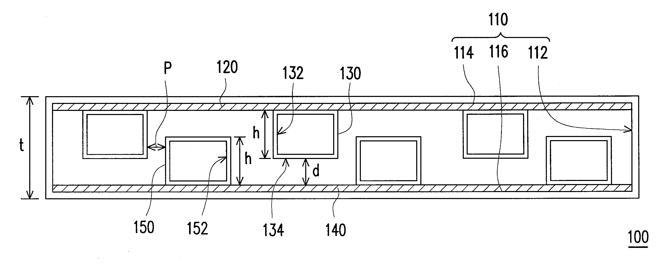
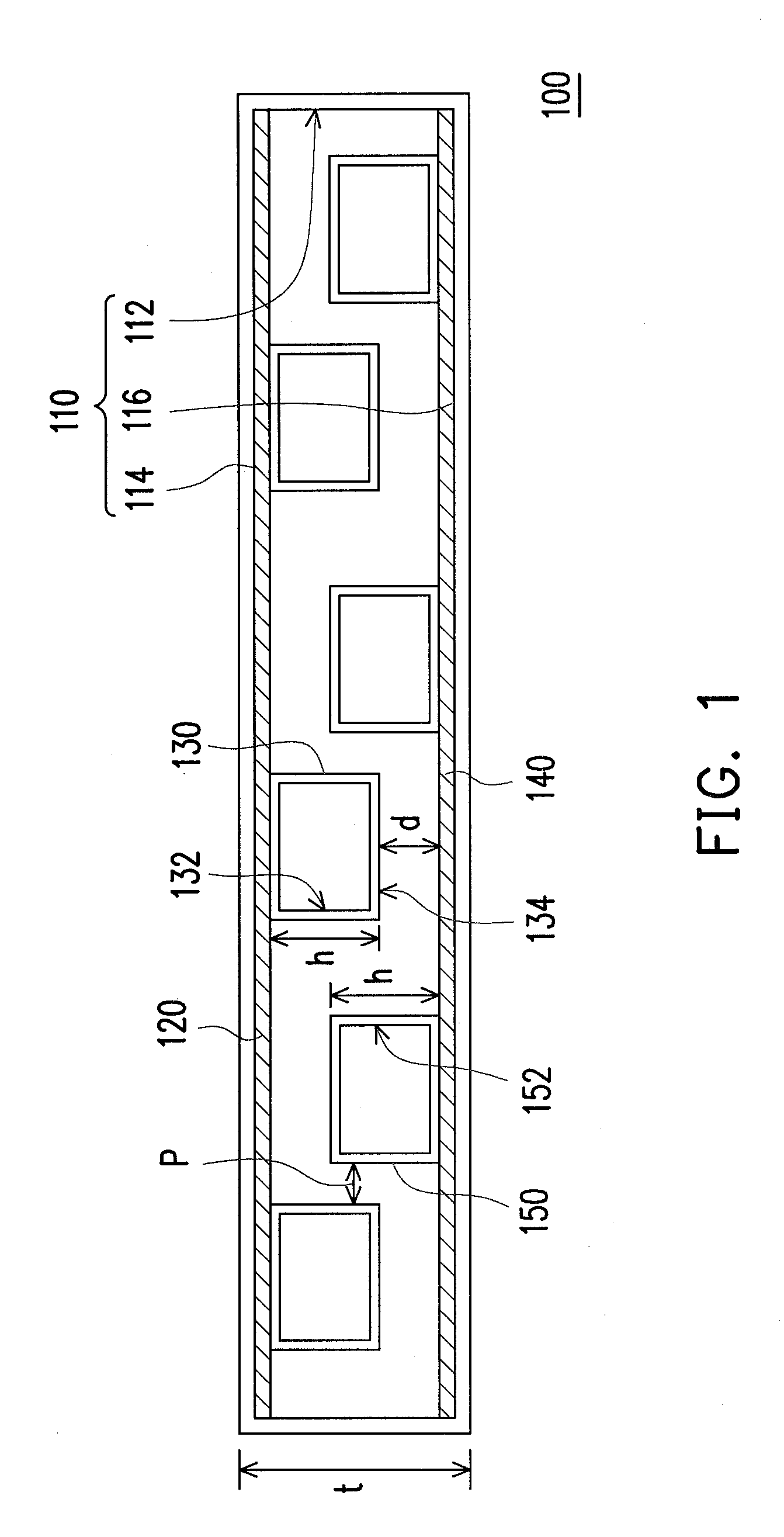
[0028]FIG. 1 is a schematic diagram illustrating a light source set according to an embodiment of the present invention. Referring to FIG. 1, the light source set 100 includes a light cover 110, a first circuit board 120, a plurality of first point light sources 130, a second circuit board 140 and a plurality of second point light sources 150. The light cover 110 has an opening 112, a first side 114 and a second side 116. The first side 114 and the second side 116 are located at two opposite sides of the opening 112. The first circuit board 120 is disposed on the first side 114. The first point light sources 130 are disposed on the first circuit board 120, and each first point light source 130 has a first light-emitting surface 132 facing to the opening 112 and a first top surface 134 surface 134 departing from the first circuit board 120. The second circuit board 140 is disposed on the second side 116, and is substantially parallel to the first circuit board 120. The second point l...


PUM


Abstract

A light source set including a light cover has an opening, a first side and a second side, a first circuit board disposed on the first side, a plurality of first point light sources disposed on the first circuit board, a second circuit board disposed on the second side and a plurality of second point light sources disposed on the second circuit board is provided. The first side and the second side are located at two opposite sides of the opening. Each first point light source has a first light-emitting surface facing to the opening and a first top surface departing from the first circuit board. Each second point light source has a second light-emitting surface facing to the opening. A distance between the first top surface and the second circuit board is smaller than a height of the second point light sources.

Description

CROSS-REFERENCE TO RELATED APPLICATION[0001]This application claims the priority benefit of Taiwan application serial no. 97135342, filed on Sep. 15, 2008. The entirety of the above-mentioned patent application is hereby incorporated by reference herein and made a part of this specification.BACKGROUND OF THE INVENTION[0002]1. Field of the Invention[0003]The present invention relates to a light source set and a backlight module. More particularly, the present invention relates to a light source set and a backlight module having point light sources disposed on different circuit boards.[0004]2. Description of Related Art[0005]With great improvement of computer performance and quick development of Internet and multimedia techniques, transmission of image information is changed from analog transmission to digital transmission. To comply with a modern life, sizes of video or image devices are gradually lighter and thinner. Though a conventional cathode ray tube (CRT) display still has its...

Claims


Application Information

Patent Timeline
Patent Type & Authority Applications(United States)
IPC IPC(8): F21V7/22B60Q1/26
CPCG02B6/0068G02B6/0083G02B6/009H05K2201/10106H05K1/189H05K2201/042H05K2201/09063H05K1/144
Inventor CHANG, CHIA-CHUN
Owner CHUNGHWA PICTURE TUBES LTD
Why Eureka
Try Eureka