Brush seal for a turbo-machine

a turbo-machine and brush seal technology, which is applied in the direction of machines/engines, stators, liquid fuel engines, etc., can solve the problems of inability to support bristles as near, limit the tolerable pressure difference of known brush seals, etc., and achieve the effect of avoiding distortion and increasing the rigidity of the pla

Inactive Publication Date: 2010-03-18
SIEMENS AG
View PDF7 Cites 43 Cited by
  • Summary
  • Abstract
  • Description
  • Claims
  • Application Information

AI Technical Summary

Benefits of technology

[0022]The film or disk preferably has a structure for supporting the bristles. By virtue of this measure which can be implemented comparatively easily, the rigidity of the plate can be further increased. In this case, the film or disk is essentially bent in its longitudinal direction, in order thereby to avoid distortion.

Problems solved by technology

Nevertheless, the abovementioned limits continue to be placed on the tolerable pressure difference of known brush seals.
In particular, because of the radial play necessary between the rotating and the stationary components, the bristles cannot be supported as near as is desired to an opposite component by means of a guide plate or a supporting ring.

Method used


Image

  • Brush seal for a turbo-machine
  • Brush seal for a turbo-machine
  • Brush seal for a turbo-machine

Examples


Embodiment Construction

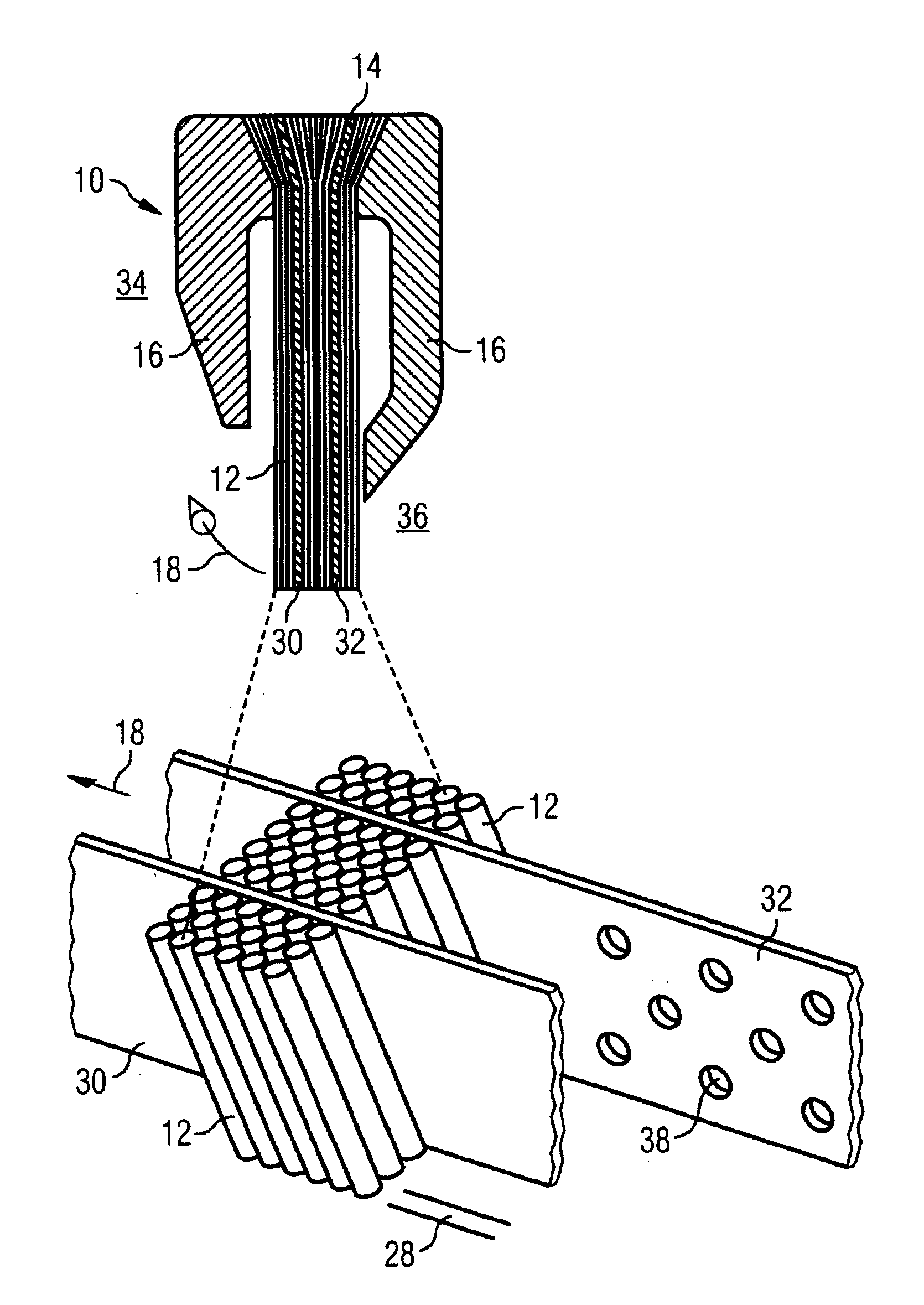
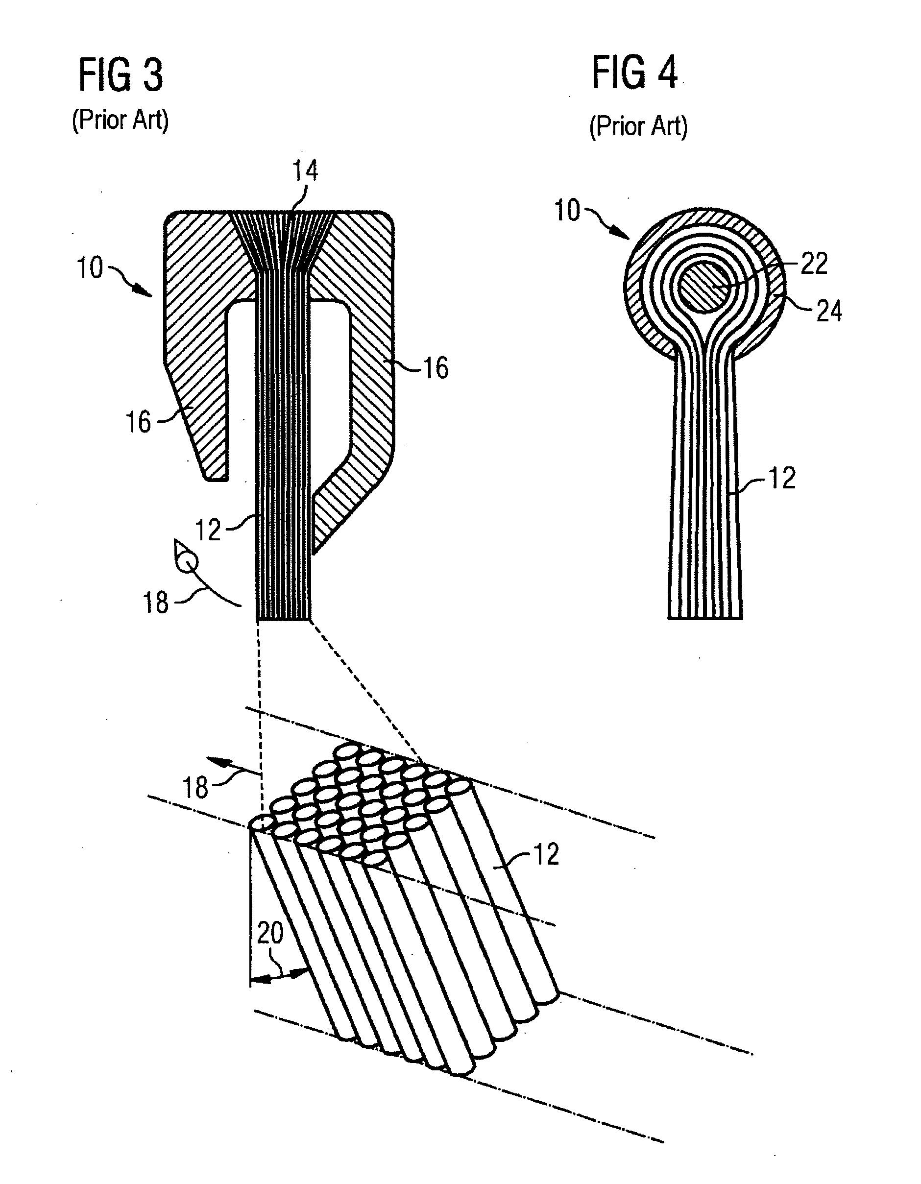
[0036]FIG. 3 makes clear a brush seal 10 of the prior art which has bristles 12 extending essentially parallel and together forming a bristle bundle. The bristles 12 are embedded into a basic body 14 which is located between two guide plates 16. The guide plates 16 extend individually in the longitudinal direction of the bristles 12, the guide plate 16 located on the right with respect to FIG. 3 being curved with its lower end region in the direction of the bristles 12 and supporting the bristles 12 at their lower end region. When the brush seal 10 of this type is rotated in the direction of an arrow 18, the lower end regions of the bristles 12, with respect to FIG. 3, undergo frictional resistance against an opposite stationary component (not illustrated in any of FIGS. 3 to 6), and the bristles 12 are thereby curved at an angle 20 opposite to their main direction of movement.

[0037]FIG. 4 makes clear an exemplary embodiment of a brush seal 10 according to the prior art in which bri...


PUM


Abstract

A brush seal for a turbo-machine for sealing a gap between a rotating and a stationary component is disclosed. Elastically flexible bristles are arranged in a plurality of rows that are adjacent to each other. A film or a disk is arranged between at least two rows of bristles, the film or the disk extending in the longitudinal direction of said bristles.

Description

CROSS REFERENCE TO RELATED APPLICATIONS[0001]This application is the US National Stage of International Application No. PCT / EP2007 / 058353 filed Aug. 13, 2007 and claims the benefit thereof. The International Application claims the benefits of European patent application No. 06017253.3 EP filed Aug. 18, 2006, both of the applications are incorporated by reference herein in their entirety.FIELD OF INVENTION[0002]The invention relates to a brush seal for a turbo-machine for sealing off a gap between a rotating and a stationary component of the turbo-machine, in which brush seal elastically flexible bristles are provided in a plurality of bristle rows arranged next to one another.BACKGROUND OF INVENTION[0003]In turbo-machines having rotating and stationary components, sealing elements of various types of construction are used for sealing off various pressure spaces. In this case, in particular, contactless seals (for example, labyrinth seals) or resilient contacting sealing elements are...

Claims


Application Information

Patent Timeline
Patent Type & Authority Applications(United States)
IPC IPC(8): F01D11/00F16J15/44
CPCF16J15/3288F01D11/001
Inventor BRUCK, STEFANNEEF, MATTHIASSULDA, ERIKSURKEN, NORBERT
Owner SIEMENS AG
Why Eureka
Try Eureka