
Optical film

Inactive Publication Date: 2010-03-18
ETERNAL MATERIALS CO LTD
View PDF1 Cites 28 Cited by
  • Summary
  • Abstract
  • Description
  • Claims
  • Application Information

AI Technical Summary

Benefits of technology

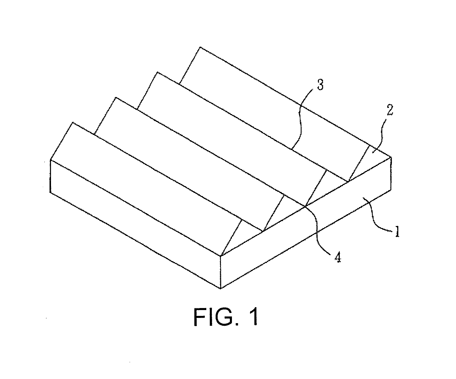
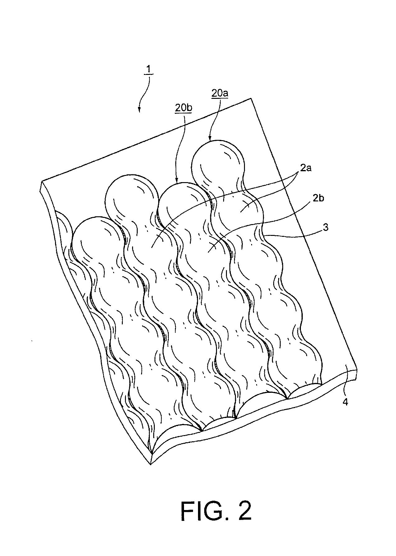
[0010]The optical film according to the present invention provides a specific structure which can block and confine the organic particles so as to reduce aggregation or adhesion of said organic particles and to render the particles orderly arranged. The optical film according to the present invention can converge and diffuse light rays, thereby enhancing the uniformity of the light rays and increasing the luminance.
[0011]In another aspect, the present invention provides a method for producing an optical film having microstructures by a continuous roll-to-roll technique. The method according to the present invention greatly increases the industrial applicability of the optical film.

Problems solved by technology

The prisms of a brightness enhancing film could be easily scratched when contacting the display panel or other films, adversely affecting the optical characteristics of the prisms.
Use of protective diffusion film and other protective films, however, increases manufacturing cost.
However, not all of the light rays are effectively utilized due to the randomness of the scattering.
In addition, during the process of production, diffusion particles might aggregate or adhere to each other, reducing uniformity of the diffused light rays and potentially resulting in a dark spot on the display.
Moreover, brightness enhancing film is expensive relative to other optical films.
Manufacturing throughput according to this method is low, however, so its industrial applicability is limited.
Accordingly, the structure cannot be produced by non-stop roll-to-roll processes such as slot die coating or roller coating.

Method used


Image

  • Optical film
  • Optical film
  • Optical film

Examples


Embodiment Construction

[0025]It should be understood that the detailed description, while indicating the preferred embodiments of the invention, is intended for purposes of illustration only and is not intended to limit the scope of the invention. For example, in the present disclosure, the words “a” and “an” are, unless otherwise indicated, to be taken to include both the singular and the plural.

[0026]In the context of the disclosure, the term “columnar structure” may represent a prismatic columnar structure, an arc-shaped columnar structure or a mixture thereof.

[0027]In the context of the disclosure, the term “prismatic columnar structure” represents a columnar structure having two slant surfaces that are flat. The slant surfaces meet at the top of a prism to form a peak, or are blunted to form a blunt-shaped surface.

[0028]In the context of the disclosure, the term “arc-shaped columnar structure” represents a columnar structure having two slant surfaces that are curved. The two slant surfaces meet at th...


PUM

PropertyMeasurementUnit
Fractionaaaaaaaaaa
Percent by massaaaaaaaaaa
Thicknessaaaaaaaaaa

Abstract

The present invention relates to an optical film comprising a substrate having microstructures and a resin coating disposed on the microstructures of the substrate. The resin coating comprising a plurality of organic particles and a binder. The microstructures comprise a plurality of columnar structures which are equilateral, and the organic particles are tangent to the columnar structures. The height of the organic particles is not less than the height of the columnar structures. The optical film of the present invention enables the organic particles to be uniformly and orderly distributed so that the transmitting light is homogenized and the brightness can be enhanced.

Description

BACKGROUND OF THE INVENTION[0001]1. Field of the Invention[0002]The present invention relates to an optical film. In particular, the present invention relates to an optical film having highly uniform optical characteristics, and which is useful in a backlight module.[0003]2. Description of the Prior Art[0004]It is known that liquid crystal display (LCD) panels do not independently emit light. To properly display an image, a backlight module is required to serve as a light source providing sufficient and uniform brightness. A typical backlight module uniformly distributes and converges light rays by utilizing a diffusion plate, a diffusion film and a brightness enhancing film. The function of the diffusion plate and diffusion film is to provide a uniform area light source while the brightness enhancing film, also known as brightness enhancement film or prism film, converges the scattered light rays by refraction and internal total reflection, and converges the rays in the on-axis dir...

Claims


Application Information

Patent Timeline
IPC IPC(8): B32B5/16B32B27/00
CPCG02B3/0043G02B3/0062G02B5/0215Y10T428/24405G02B5/045Y10T428/24372G02B5/0226
Inventor WANG, YI-CHIAHU, JUI-KAI
Owner ETERNAL MATERIALS CO LTD
Learn More