Wireless interface

a wireless interface and cable technology, applied in the field of wireless interfaces, can solve the problems of increasing the number of external connections, adding a significant cost in the manufacture of the display, and the complexity of the display system, so as to achieve the effect of providing sufficient power, sufficient bandwidth, and high speed

Active Publication Date: 2010-03-18
SHARP KK
View PDF18 Cites 56 Cited by
  • Summary
  • Abstract
  • Description
  • Claims
  • Application Information

AI Technical Summary

Benefits of technology

[0032]It is thus possible to provide an arrangement which permits completely wireless interfacing of all signals and power between transmitting and receiving sections. For example, in the case of a display, it is possible to supply sufficient power for all power requirements of a display together with all signaling, such as data, timing and control signals. It is po

Problems solved by technology

Attaching this cable adds a significant cost in the manufacture of the display.
The increase in the complexity of the display system inevitably leads to a corresponding increase in the number of external connections which results in a bigger FPC connector.
However, products incorporating these display systems are becoming physically smaller in size and there is therefore pressure to find alternative methods of transmitting the signals to the display system.
If the bandwidth available in these systems is less than the signal bandwidth, then the signal will lose some information and can lead to erroneous decoding of the transmitted data.
However, the difficulty arises when an application requires both power and data to be transmitted wirelessly across the same wireless channel.
The implication is that it is more difficult to recover both power and data if the data signal has high bandwidth.
Increasing Q improves the power transferring capability of the s

Method used


Image

  • Wireless interface
  • Wireless interface
  • Wireless interface

Examples


Embodiment Construction

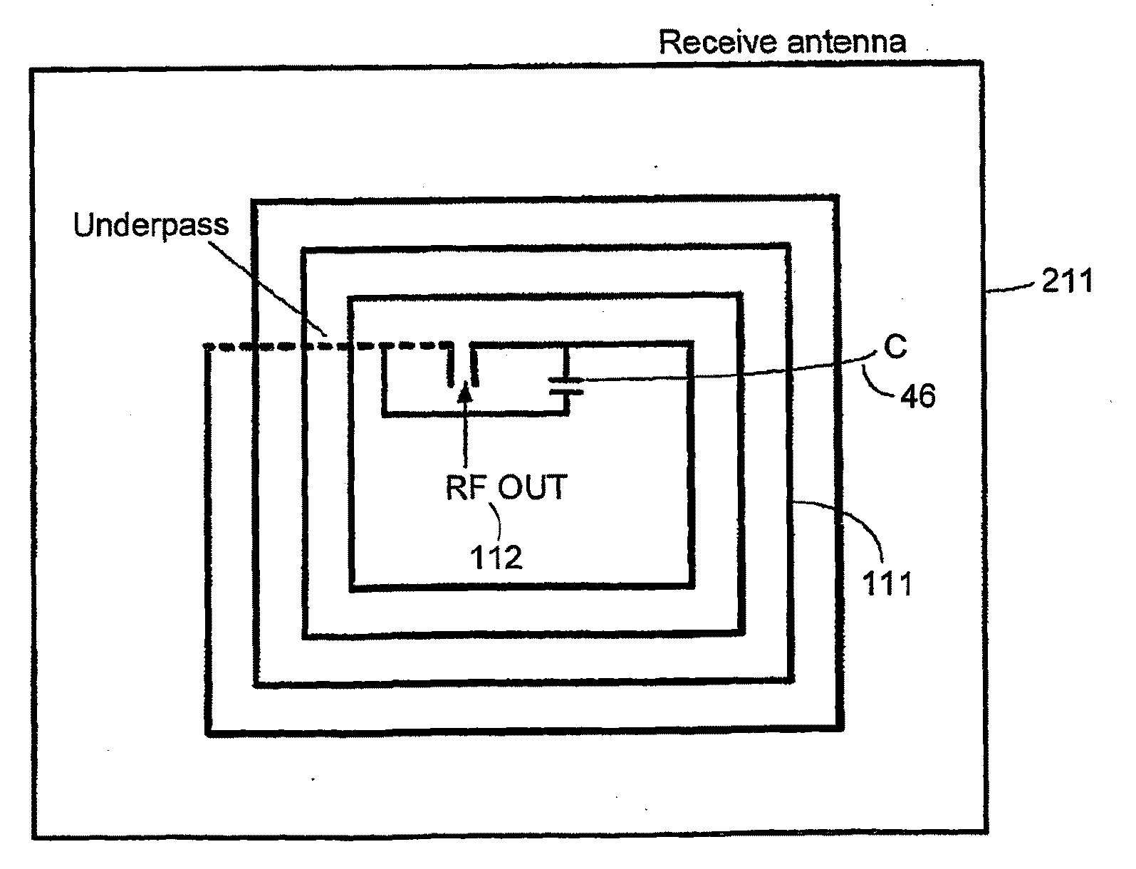
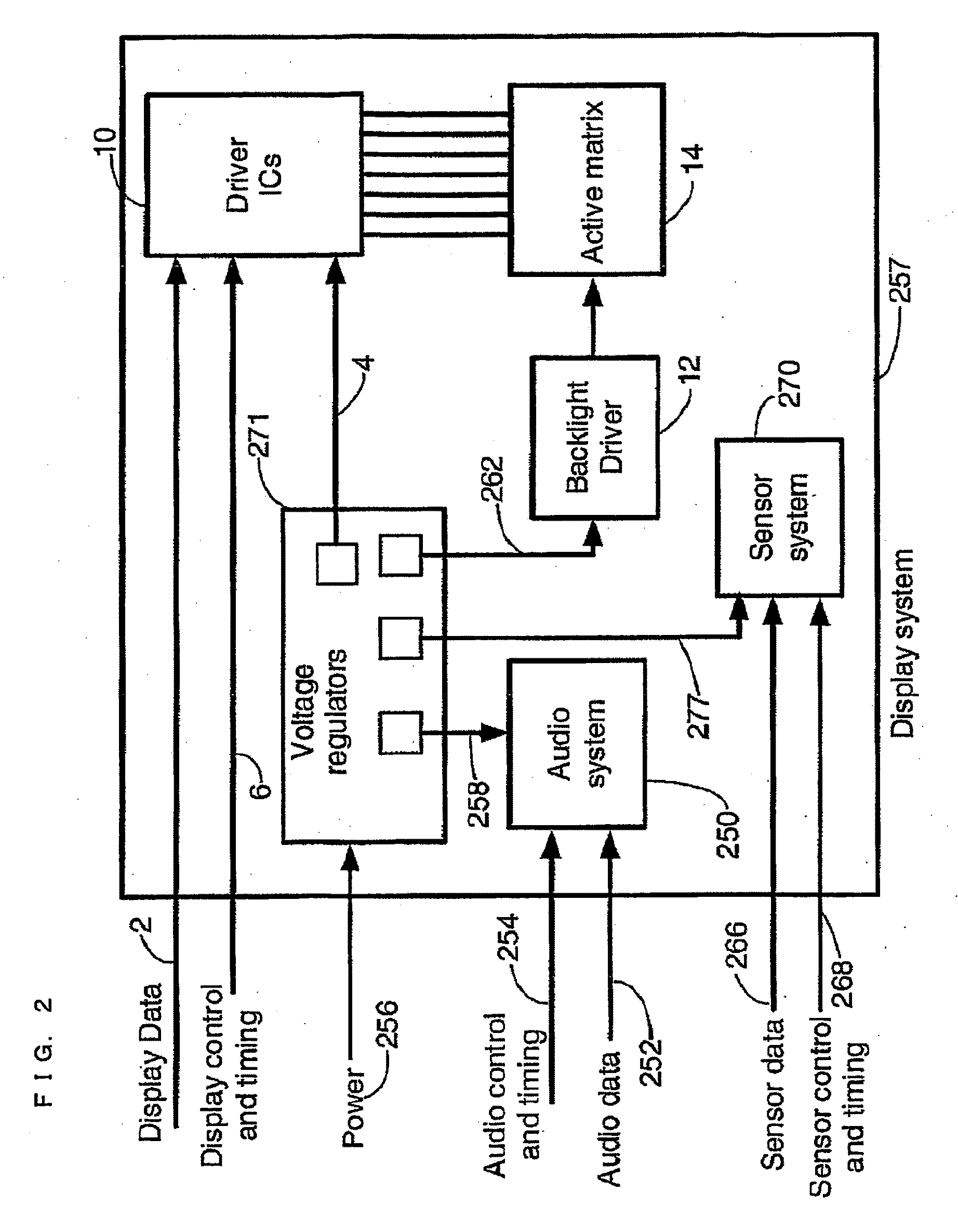
[0078]FIG. 23 shows a complete wireless system comprising a driver system 200 constituting a transmitting section and a wireless display system 220 constituting a receiving section. The driver system 200 comprises a data source 202 to supply the display system data 212 and the control and timing signals 208. These signals are then connected to the transmitter system 210 which is then connected to a transmit antenna 166. The driver system 200 is supplied with power 204 externally to power all the circuitry. After the signal is launched from the transmit antenna 210, it traverses the wireless channel 26 to couple to the wireless display system 220. The wireless display system comprises the receive system 224 which is connected to the display system 257. A receive antenna 211 which captures the transmitted signal is connected to a receiver 255. The receiver extracts the display system data 212, control and timing signals 208 and power 256 from the transmitted signal. These signals are ...


PUM


Abstract

In one embodiment of the present invention, a wireless interface is provided for supplying all signals and power exclusively wirelessly from a transmitting section to a receiving section. The transmitting section includes a transmitter arranged to modulate a carrier with signals, such as data, control and timing signals. The transmitter is connected to a transmit antenna which comprises a parallel resonant circuit in series with a series resonant circuit. The parallel and series resonant circuits include inductors which are inductively coupled to an inductor of a receive antenna in the receiving section.

Description

TECHNICAL FIELD[0001]The present invention relates to a wireless interface. For example, such an interface may be used for supplying data and power wirelessly within a display system, for example including a flat panel display of liquid crystal or organic light emitting diode type. Another example of an application of such an interface is in a radio frequency identification system. The present invention also relates to a transmitting section and to a receiving section for such an interface.BACKGROUND ART[0002]FIG. 1 of the accompanying drawings shows a generic liquid crystal display system which is an example of a flat panel display. Such a display is made up of an active area including an active matrix 14 which displays the image, a backlight system including a driver 12 to illuminate the display and a number of driver integrated circuits (ICs) 10 to control the addressing of pixels. The system is supplied with the display data 2, a number of control and timing signals 6 and power ...

Claims


Application Information

Patent Timeline
IPC IPC(8): H04B5/00H04B7/00H04B1/02H04B1/16
CPCH01F17/0006H02J5/005H01F2038/143H01F19/04H02J50/12G01V15/00H01F38/14H02J50/80H02J50/20
Inventor ZYAMBO, EMMANUELLUKAMA, LLOYDBROWN, CHRISTOPHER JAMESBROWNLOW, MICHAEL JAMESMIYATA, KAZUHIKO
Owner SHARP KK
Why Eureka
Try Eureka