

Spindle drive coupling
a technology of drive coupling and spindle, which is applied in the direction of fishing, manufacturing tools, portable drilling machines, etc., can solve the problems of heavy, environmental damage, bulky metal augers driven with internal combustion engines, etc., and achieve the effect of preventing inadvertent separation and light weigh
- Summary
- Abstract
- Description
- Claims
- Application Information
AI Technical Summary
Benefits of technology
Problems solved by technology
Method used
Image

Examples
Embodiment Construction
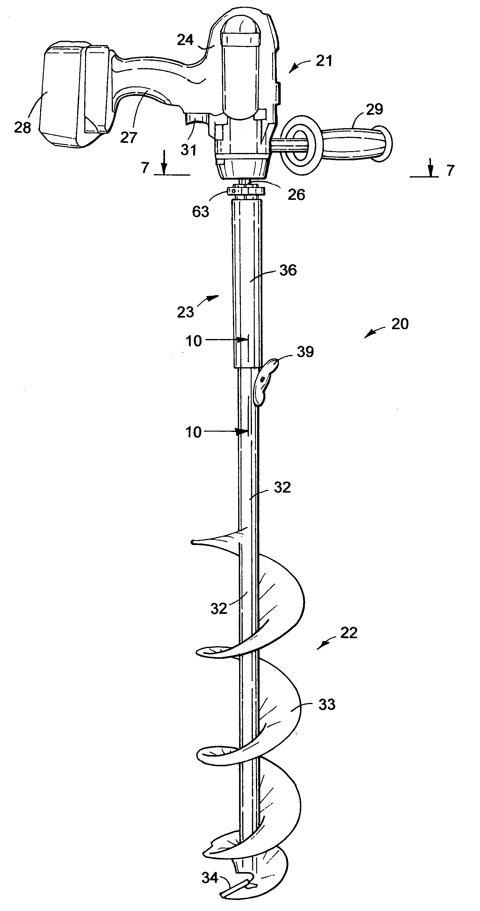
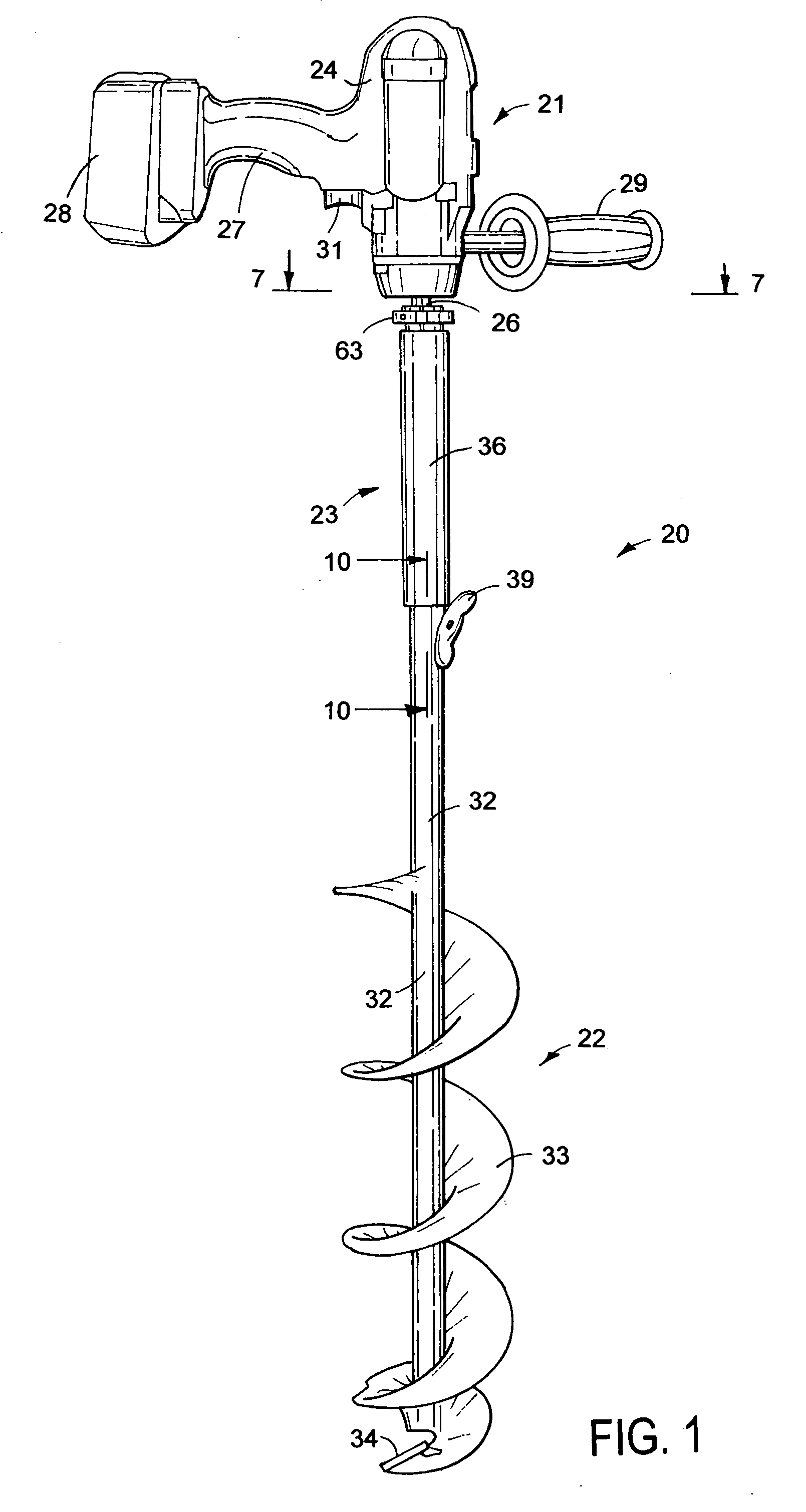
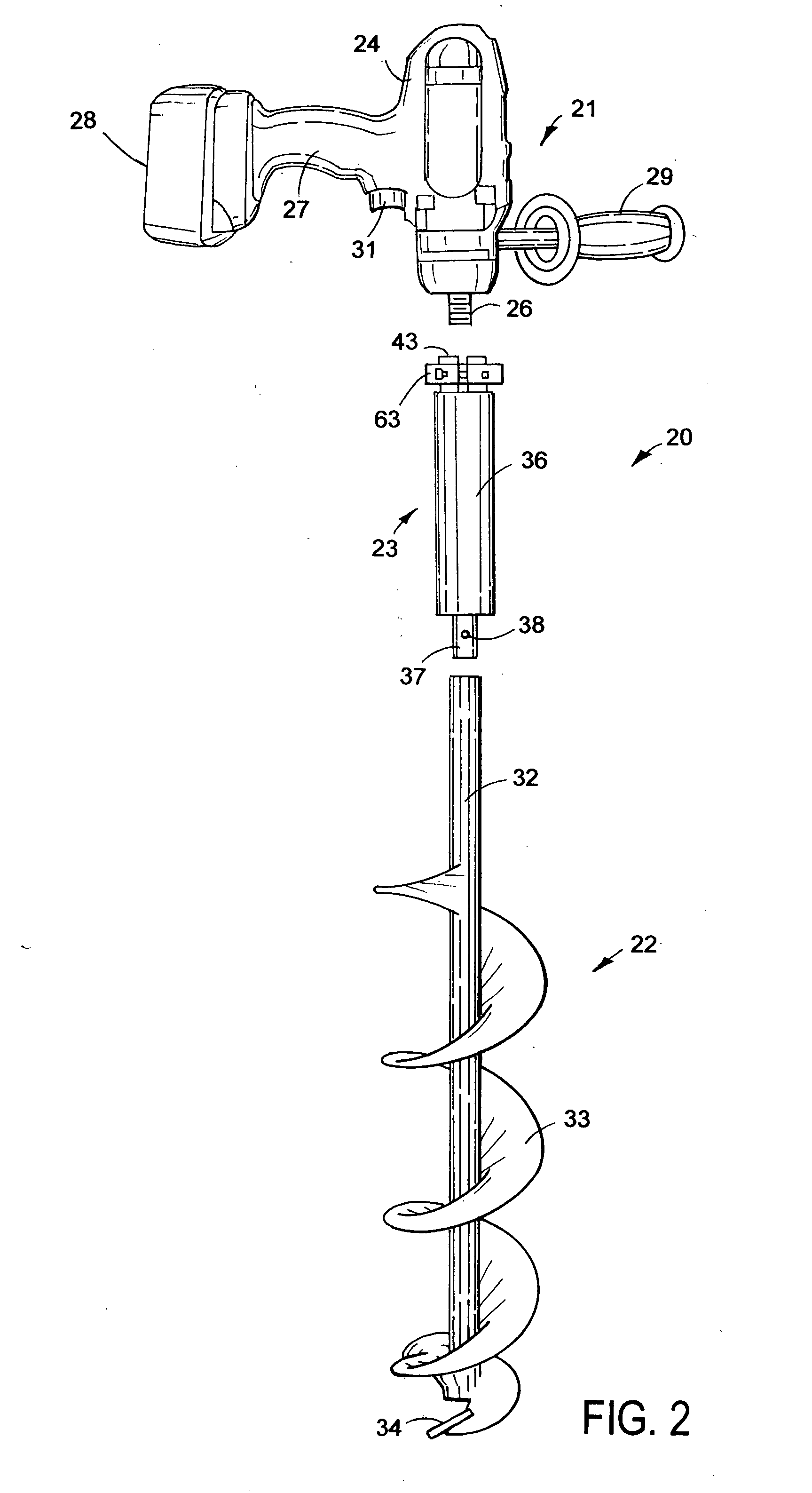
[0024]As shown in FIGS. 1 and 2, a power tool 20 is equipped with a spindle drive coupling 23 that allows a cordless electric motor 21 to be releasably attached to the coupling to allow electric motor 21 to be used for other purposes. Spindle drive assembly 23 connects electric motor 21 to an auger assembly 22. Motor 21 is a conventional d.c. electric motor having a housing 24 joined to a lateral arm 27. Motor 21 has a downwardly extended threaded drive shaft 26. The conventional Jacobs chuck has been removed from shaft 26. A battery 28 is mounted on the outer end of arm 27. One type of battery is a 36 volt lithium battery pack. Other types of power supplies and batteries can be used to operate motor 21. Battery 28 provides the energy necessary to rotate auger assembly 22 to drill an ice fishing hole in ice on a body of water. Power tool 20 with electric motor 21 is a lightweight, quiet, fast and efficient drilling machine. Power tool 20 is environmentally advantageous as it does no...
PUM
| Property | Measurement | Unit |
|---|---|---|
| electric power | aaaaa | aaaaa |
| temperatures | aaaaa | aaaaa |
| thickness | aaaaa | aaaaa |
Abstract
Description
Claims
Application Information