Electrode

a technology of electrodes and electrodes, applied in the field of electrodes, can solve the problems of affecting the performance of the electrode, the impedance reduction of the electrode, and the inability to achieve sufficient reduction of the electrode, and achieve the effect of high adhesion and low impedan

Inactive Publication Date: 2010-03-25
TDK CORPARATION
View PDF2 Cites 9 Cited by
  • Summary
  • Abstract
  • Description
  • Claims
  • Application Information

AI Technical Summary

Benefits of technology

[0009]According to the present invention, the angle between each of the projections extending from the current collector of the electrode and the surface of the current collector is in the range of 30 to 80° and the inclined projections are surrounded by the active material layer; therefore, a physical anchor effect is achieved, so as to realize high adhesion between the current collector and the active material layer. Since the projections are inclined relative to the surface of the current collector, the distance becomes shorter between the current collector including the projections, and the active material, which was located apart from the projections extending perpendicularly to the surface of the current collector in the conventional technology. Therefore, the electrically conducting paths become shorter and the impedance is reduced.
[0011]A ratio of a distance between a tip of the projection and the surface of the current collector to a thickness of the active material layer is preferably in the range of 0.24 to 0.99. In this case, it is feasible to suitably maintain the high adhesion between the current collector including the projections, and the active material layer and to more effectively reduce the impedance.

Problems solved by technology

The technology described in Patent Literature 1 improves the adhesion between the current collector and the active material layer because of the existence of the curves or burrs on the surface of the current collector, but has a problem that there is variation in electrically conducting paths between the active material in the active material layer and the current collector.
However, the active material located away from the curves or burrs is distant from the current collector and the electrically conducting paths become longer.
As a result, the electrode failed to achieve sufficient reduction in impedance and it was a hindrance to further improvement in output characteristics.

Method used


Image

  • Electrode
  • Electrode
  • Electrode

Examples


example 1

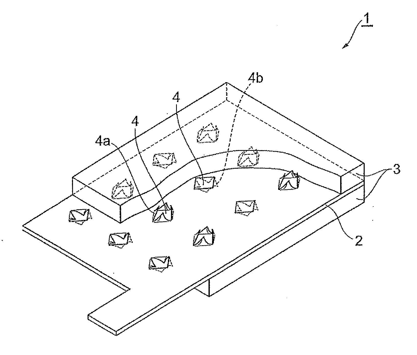
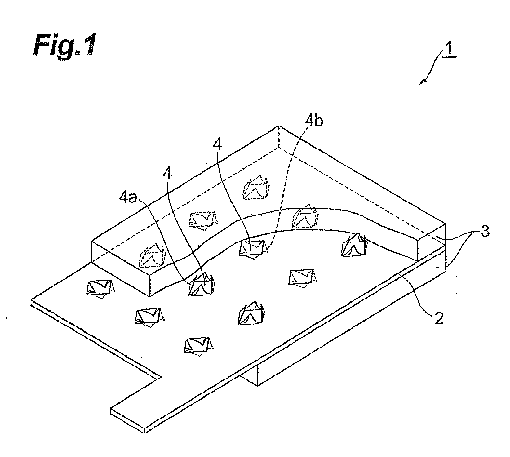
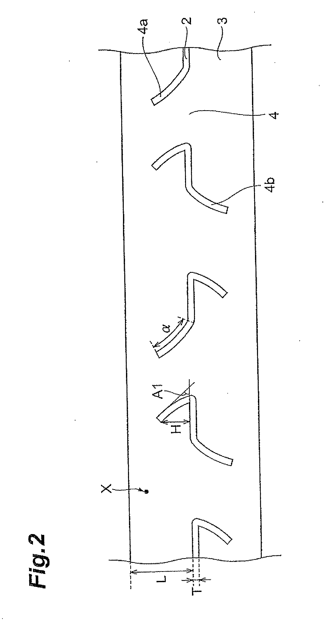
[0057]A copper current collector sheet 20 μm thick was perforated to form rhombic through holes with the length of projections (burrs) being 70 μm in such arrangement that the rhombic through holes were alternately projecting at equal intervals of 500 μm from the top and back sides. The projections of this current collector sheet were inclined using the aforementioned electrode producing apparatus 100 and then the coating solution was applied onto the collector sheet to form the active material layer, thereby producing an electrode. At this time, the diameter of the nip roll 22 in the electrode producing apparatus 100 was 120 mm, the diameter of the backup roll 21 was 120 mm, and the line speed was 8 mm / min. The coating solution for formation of the active material layer was a solution obtained by mixing and dispersing 90 parts by mass of black lead (trade name: OMAC available from Osaka Gas Co., Ltd.) and 1 part by mass of graphite (trade name: KS-6 available from LONZA) as an acti...


PUM

PropertyMeasurementUnit
angleaaaaaaaaaa
angleaaaaaaaaaa
widthaaaaaaaaaa

Abstract

An electrode has a current collector having a plurality of through holes, and active material layers provided on both sides of the current collector, the current collector has projections extending on the top side or on the back side of the current collector from respective edges of the through holes, and an angle between each of the projections and a surface direction of the current collector is in the range of 30 to 80°. Because of the configuration wherein the projections are surrounded by the active material layers, a physical anchor effect is achieved so as to provide high adhesion. Since the projections are inclined relative to the surface direction of the current collector, the distance becomes shorter between the current collector including the projections and an active material, which was located apart from the projections in the case where the projections extended perpendicularly to the surface direction of the current collector. Therefore, electrically conducting paths become shorter and impedance is reduced.

Description

BACKGROUND OF THE INVENTION[0001]1. Field of the Invention[0002]The present invention relates to an electrode.[0003]2. Related Background Art[0004]Electrochemical devices such as primary batteries, secondary batteries (particularly, lithium-ion secondary batteries), electrolysis cells, and capacitors (particularly, electrochemical capacitors) are widely used in various fields. An electrode for such electrochemical devices is constructed normally in such a structure that an active material layer is laid on a plate-like current collector having through holes and this active material layer contains a large number of particles containing an active material.[0005]It is important for the foregoing electrode to improve adhesion between the current collector and the active material layer, in order to achieve improvement in performance. For this reason, a variety of techniques have been researched in order to improve the adhesion between the current collector and the active material, layer. ...

Claims


Application Information

Patent Timeline
Patent Type & Authority Applications(United States)
IPC IPC(8): H01M4/02H01G11/66H01G11/70H01M4/74
CPCH01M4/661H01M4/70H01M4/742Y02E60/13H01G11/28H01G11/32H01M10/052Y02E60/10
Inventor NAOI, KATSUOEMOTO, KAZUTOSHIHINOKI, KIYONORISAEGUSA, MASAHIRONISHIZAWA, KENJIKOUGO, MITSUO
Owner TDK CORPARATION
Why Eureka
Try Eureka