Method and system for treatment of regurgitating heart valves

a technology for repairing and mitral regurgitation, applied in the field of treatment of heart valves, can solve the problems of life-threatening illness, malfunction of a person's heart valve, and still has about 25-30% failure rate in the repair of mitral regurgitation from a damaged and/or enlarged heart, and achieve the effect of preventing possible buckling of the leafl

Inactive Publication Date: 2010-03-25
DRAKE DANIEL H
View PDF6 Cites 10 Cited by
  • Summary
  • Abstract
  • Description
  • Claims
  • Application Information

AI Technical Summary

Benefits of technology

[0007]In accordance with the present invention, reductive ring annuloplasty is utilized in combination with a patch applied to the anterior leaflet. This technique compresses the heart valve tissue laterally and advances the leaflet tissue to close the valve and prevent MR.
[0008]The heart valve is first measured and analyzed and a determination is made as to the amount of lateral compression of the valve that is needed. A D-shaped plasty patch is made or selected of the appropriate size and shape for the amount of advancement needed. Once stitches are positioned around the valve for subsequent use in securing an annuloplasty ring, an incision is made on the leaflet of the mitral valve of a predetermined length. To prevent possible buckling of the leaflet, “keystone”-shaped D-plasty patches can be utilized, and / or specifically shaped annuloplasty rings.
[0009]A D-shaped plasty patch is stitched in place in the opening in the leaflet created by the incision. Thereafter, the ring is secured in place and the valve annulus is compressed to its final position. The annuloplasty ring in particular compresses the valve in the lateral direction. The advancement of the leaflet caused by such lateral compression in combination with the additional D-plasty patch extends the leaflet tissue and allows the mitral valve to close as it should during normal function. Specifically shaped annuloplasty rings can also be used to assist in providing full closure of the valve.

Problems solved by technology

A malfunction of a person's heart valve such as mitral regurgitation, can be a life threatening illness.
Although many of these systems and techniques have been successful and have allowed patients to return to relatively normal lifestyles, there still is about a 25-30% failure rate in the repair of mitral regurgitation from a damaged and / or enlarged heart.

Method used


Image

  • Method and system for treatment of regurgitating heart valves
  • Method and system for treatment of regurgitating heart valves
  • Method and system for treatment of regurgitating heart valves

Examples


Embodiment Construction

[0027]The present inventive process and system has particular use and applicability for repair of mitral valves in the heart and to prevent recurrent mitral regurgitation (MR). Thus, the invention will be illustrated and described with respect to MR. It is to be understood, however, that the present invention can be used relative to repair of numerous other valves in the heart, such as tricuspid valves, aortic valves and pulmonic valves. It is also possible to use an embodiment of the present invention to secure tissue advancement in other parts of the body.

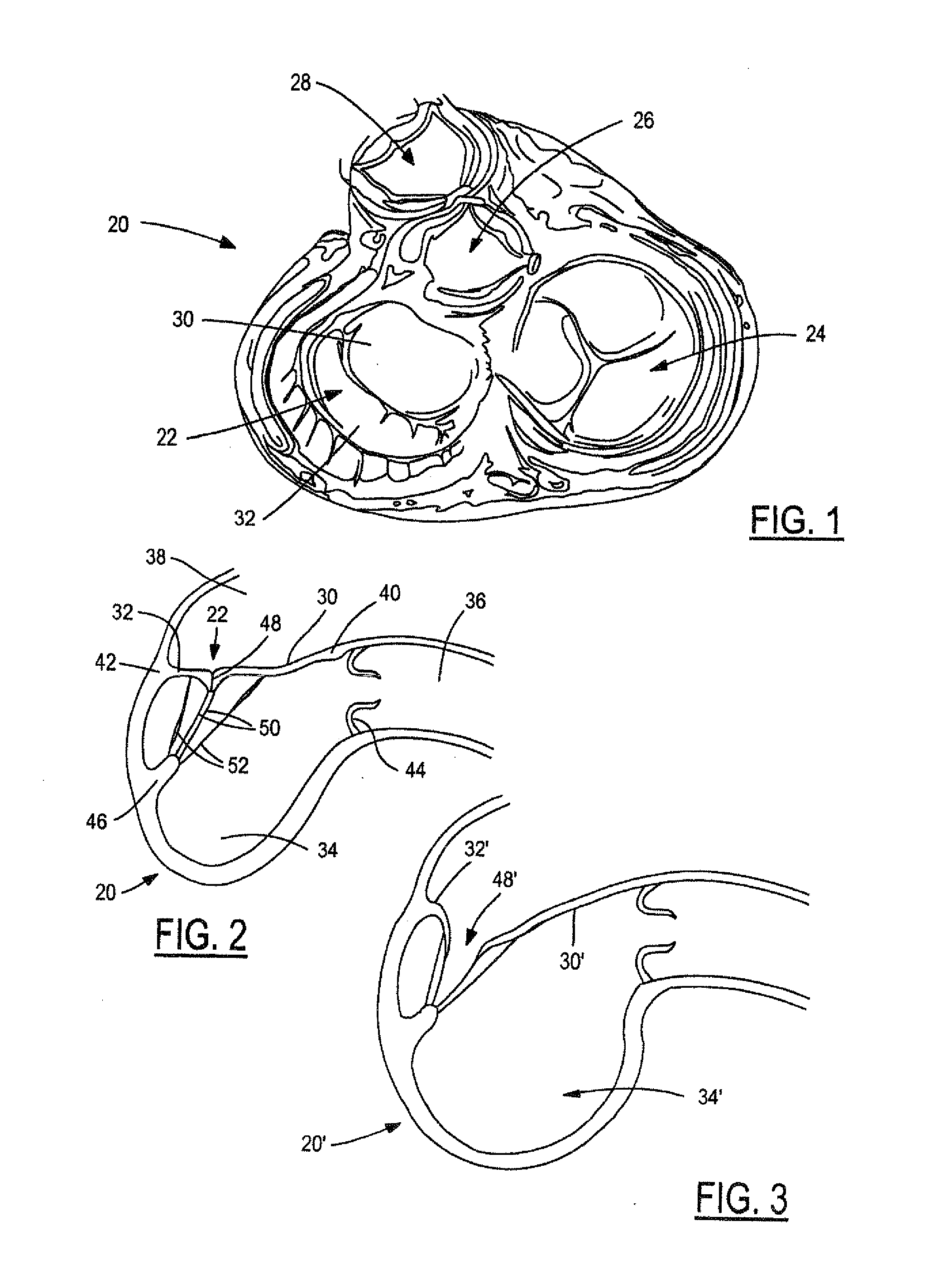
[0028]FIG. 1 is a view of a portion of a human heart 20 cut away to show the various valves. The heart 20 is viewed in systole from the base with atria removed. The valves illustrated are the mitral valve 22, the tricuspid valve 24, the aortic valve 26 and the pulmonic valve 28. The mitral valve 22 has an anterior leaflet 30 and a posterior leaflet 32.

[0029]A schematic cross-section through the left side of a normal heart 20 is s...


PUM


Abstract

A system and process for correction of regurgitation of heart valves. With mitral valves in particular, the anterior leaflet is advanced through use of a D-plasty patch and a narrow annuloplasty ring which compresses the lateral dimension of the valve. Other specifically configured annuloplasty rings can also be utilized. The sizes of the patch and ring are selected to provide a sufficient advancement of the leaflet to restore the surface of coaptation.

Description

CROSS REFERENCE TO RELATED APPLICATIONS[0001]This is a continuation-in-part of U.S. patent application Ser. No. 11 / 853,824, filed on Sep. 12, 2007, which in turn is a continuation-in-part of Ser. No. 11 / 752,094, filed on May 22, 2007.TECHNICAL FIELD[0002]The present invention relates to treatment of heart valves and more particularly to methods and systems for repair of regurgitating heart valves.BACKGROUND OF THE INVENTION[0003]A malfunction of a person's heart valve such as mitral regurgitation, can be a life threatening illness. Many systems and techniques have been developed over the years to attempt to correct the various heart valve malfunctions. These include full replacement of the valve, the use of annuloplasty rings and bands, and leaflet elongation.[0004]Although many of these systems and techniques have been successful and have allowed patients to return to relatively normal lifestyles, there still is about a 25-30% failure rate in the repair of mitral regurgitation from...

Claims


Application Information

Patent Timeline
Patent Type & Authority Applications(United States)
IPC IPC(8): A61F2/24
CPCA61F2/2448A61F2/2463
Inventor DRAKE, DANIEL H.
Owner DRAKE DANIEL H
Why Eureka
Try Eureka