High Efficiency Furnace/Air Handler Blower Housing with a Side Wall Having an Exponentially Increasing Expansion Angle

a technology of high efficiency furnace and side wall, which is applied in the direction of machines/engines, liquid fuel engines, lighting and heating apparatus, etc., can solve the problems of large amount of pressure and air flow, and achieve the effect of overcoming efficiency problems, less pressure drop, and efficient turning of the velocity head

Active Publication Date: 2010-04-01
REGAL BELOIT AMERICA
View PDF96 Cites 13 Cited by
  • Summary
  • Abstract
  • Description
  • Claims
  • Application Information

AI Technical Summary

Benefits of technology

[0003]The present invention pertains to a high efficiency furnace and a low profile furnace that each comprise a compact enclosure for residential use and an air distribution blower housing that is designed with an outer wall having an exponentially increasing expansion angle and an enlarged air outlet opening. The enlarged outlet opening slows down and spreads out the air flow from the blower housing over a greater area of the secondary heat exchanger and the primary heat exchanger of the high efficiency furnace, and over a greater area of the heat exchanger of a low profile furnace. Thus, the blower housing enables less air pressure drop through the heat exchangers, which increases the efficiency of the blower operation. The design of the blower housing also efficiently turns the velocity head of the air flow to usable static pressure at the housing air outlet. The enlarged air outlet opening of the blower housing is achieved without increasing the exterior dimensions of the blower housing whereby the blower housing is used in a compact enclosure for residential use. This is accomplished by utilizing a unique design volute outer wall of the blower housing that has a unique exponentially increasing expansion angle in the direction of air flow through the blower housing and compact relative positioning of the blower housing and heat exchangers in the furnace enclosure.
[0005]High efficiency residential natural gas powered furnaces are becoming more and more common. A furnace of this type is defined in the industry as a 90+AFUE (Annul Fuel Utilization Efficiency) furnace. A 90+ furnace converts more than 90% of the fuel supplied to the furnace to heat, with the remainder being lost through the chimney or exhaust flue. These particular types of furnaces employ a primary heat exchanger found in most any type of furnace, plus an additional secondary heat exchanger. The secondary heat exchanger increases the capacity of the furnace to convert the heat of the gas combustion to the distribution air flow from the furnace, and thereby defines the furnace as a high efficiency furnace.
[0012]As shown in FIG. 1, the typical volute outer wall 32 of the blower housing has a constant expansion angle as it extends in the fan wheel rotation direction around the fan wheel. What is meant by expansion angle is the angle at which the outer wall expands in the direction of fan wheel rotation from any point on the exterior of the outer wall 32. In the typical construction of a blower housing outer wall 32 such as that shown in FIG. 1, this expansion angle is constant for all points along the volute outer wall 32 in the rotation direction, resulting in a gradually increasing distance between the outer circumference of the fan wheel 28 and the outer wall 32 as the outer wall extends in the rotation direction around the fan wheel.
[0014]The present invention overcomes the efficiency problems associated with the constructions of prior art 90+ furnace blowers by providing a blower with a unique housing design that spreads out the distribution air flow over the secondary heat exchanger to a larger extent than the existing blowers of the prior art. This enables the blower to operate with less of a pressure drop through the heat exchangers than that of prior art blowers. The scroll design of the blower housing also efficiently turns the velocity head of the air flow through the housing to usable static air pressure. In addition, it has been found through testing that the blower housing design of the invention applied to a low profile 80+ furnace blower has a similar or superior static efficiency to that of a regular profile blower. In a similar manner to the 90+ furnace, in an 80+ furnace where the primary heat exchanger is located close to the blower housing air outlet opening, the enlarged air outlet opening of the blower housing of the invention directs air over a larger area of the primary heat exchanger than blower housings of the prior art, and thereby creates energy savings. This enables the design of the blower housing to be employed in low profile 80+ furnaces to provide an efficiency gain, even though there is no secondary heat exchanger in the low profile furnace. The improved efficiency of the blower housing enables a reduction in the exterior dimensions of the furnace enclosure in which the blower housing is used.
[0017]The blower housing of the present invention employs a fan wheel with forward curved impeller blades for low noise and for reducing the size of the fan wheel. Fan wheels with forward curved impeller blades are known to create large amounts of pressure and air flow for a relatively small size of fan wheel.

Problems solved by technology

Fan wheels with forward curved impeller blades are known to create large amounts of pressure and air flow for a relatively small size of fan wheel.

Method used


Image

  • High Efficiency Furnace/Air Handler Blower Housing with a Side Wall Having an Exponentially Increasing Expansion Angle
  • High Efficiency Furnace/Air Handler Blower Housing with a Side Wall Having an Exponentially Increasing Expansion Angle
  • High Efficiency Furnace/Air Handler Blower Housing with a Side Wall Having an Exponentially Increasing Expansion Angle

Examples


Embodiment Construction

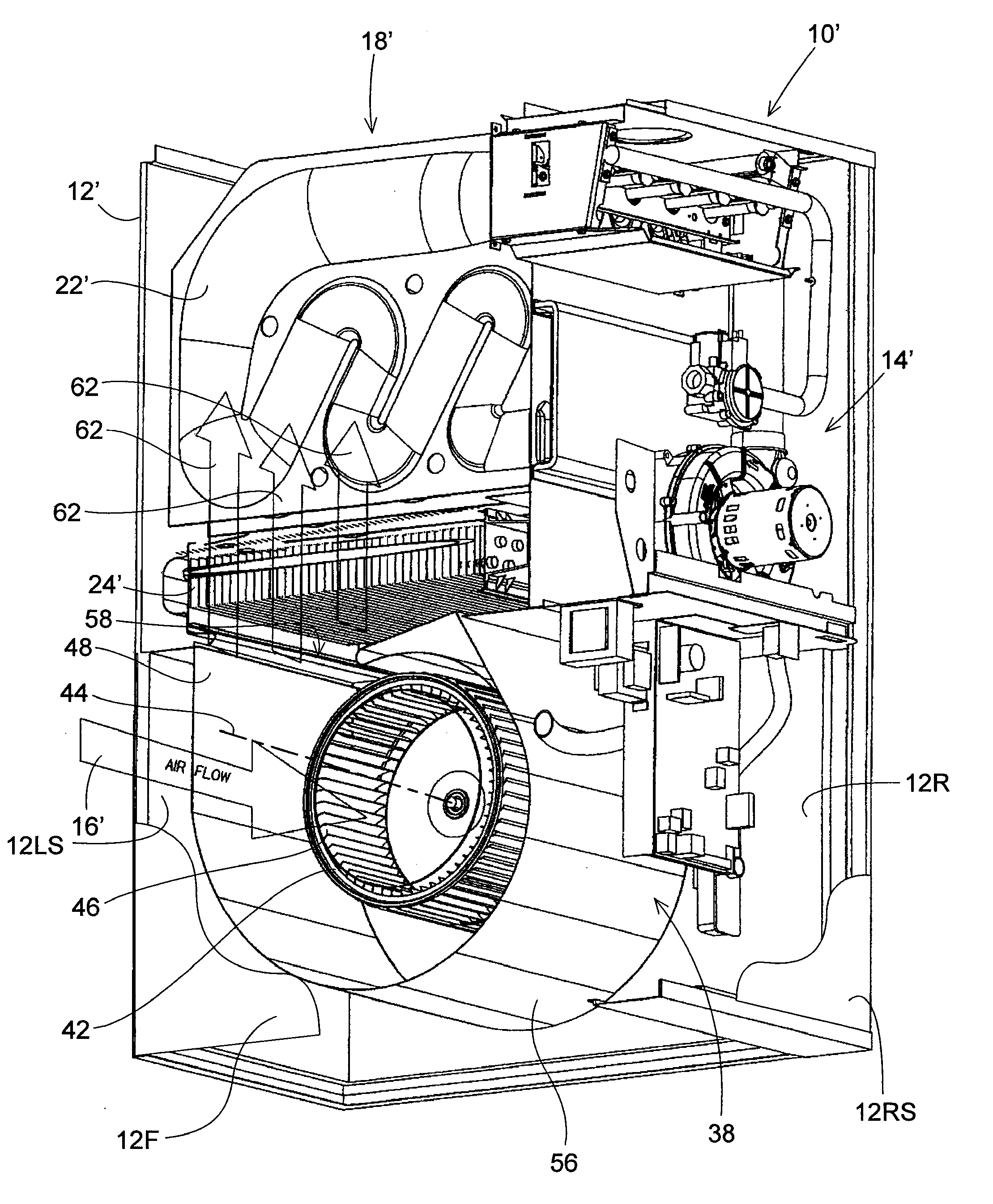
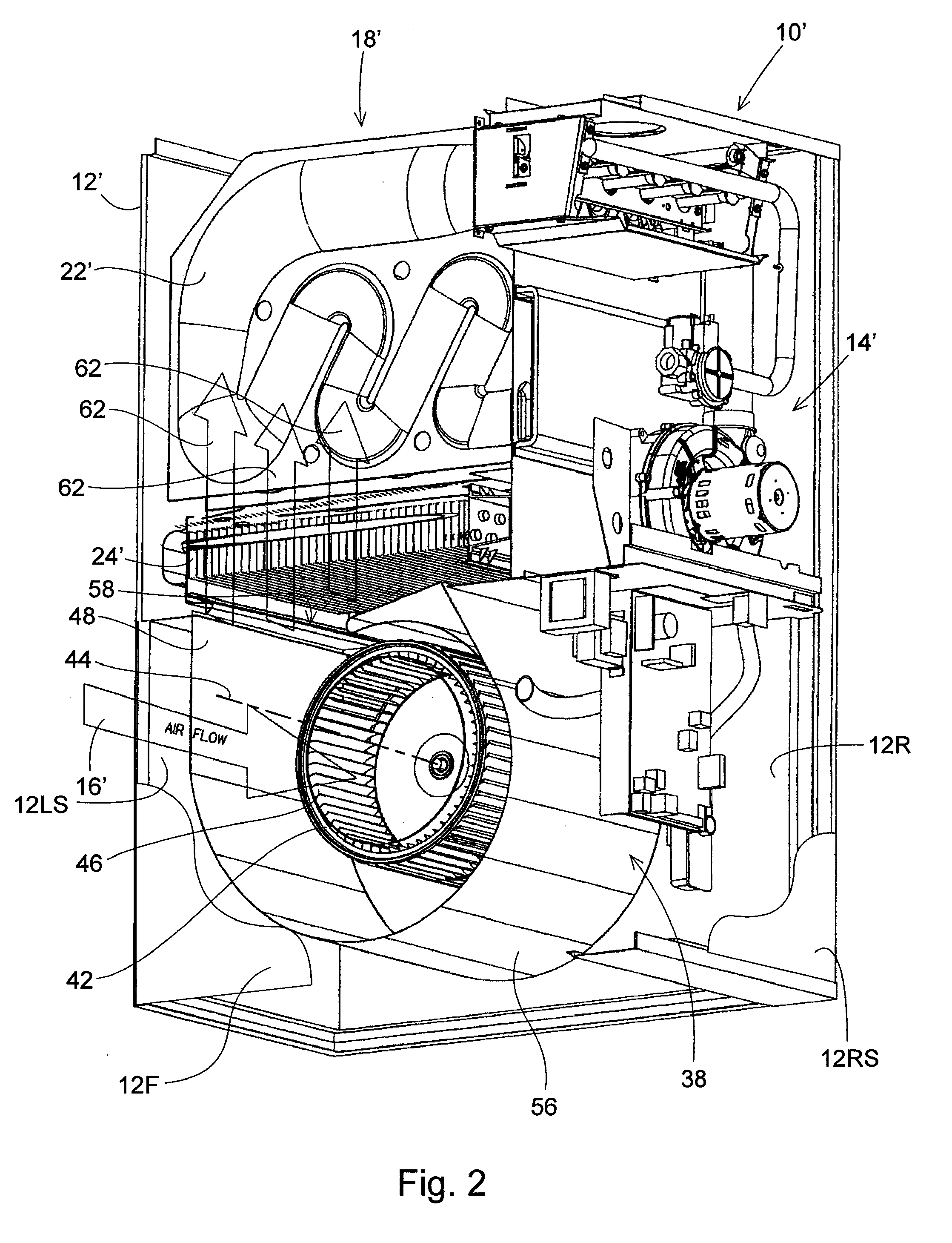
[0028]FIG. 2 is a perspective, cut away view of the high efficiency furnace of the invention that employs the blower housing of the invention having an enlarged air outlet opening and an exponentially increasing expansion angle. The furnace of the invention is primarily constructed in the same manner as known high efficiency furnaces. The difference in the furnace of the invention is in the unique design of the blower housing of the furnace. This unique design of the blower housing provides a superior distribution of air flow through the secondary and primary heat exchangers of the furnace, and thereby reduces the horsepower required by the distribution blower motor enabling an increase in the efficiency of the high efficiency furnace. Because much of the construction of the furnace shown in FIG. 2 is the same as that of FIG. 1, the same component parts of the furnace of FIG. 2 will be described only generally and are identified by the same reference numbers used in identifying the ...


PUM


Abstract

An air distribution blower housing for an air handler such as a residential furnace is designed with a volute-shaped outer wall that has an exponentially increasing expansion angle in the direction of air flow through the blower housing for at least a portion of the volute-shaped outer wall length. This results in the blower housing having an enlarged air outlet opening that slows down and spreads out the air flow from the blower housing over a greater area of the furnace heat exchanger. The blower housing thereby enables less air pressure drop through the heat exchanger, which increases the efficiency of the blower motor operation. The design of the blower housing also efficiently turns the velocity head of the air flow through the housing to usable static air pressure at the housing air outlet.

Description

RELATED APPLICATION DISCLOSURE[0001]This patent application is a continuation-in-part of patent application Ser. No. 11 / 935,726, which was filed on Nov. 6, 2007, and is currently pending.BACKGROUND OF THE INVENTION[0002]1. Field of the Invention[0003]The present invention pertains to a high efficiency furnace and a low profile furnace that each comprise a compact enclosure for residential use and an air distribution blower housing that is designed with an outer wall having an exponentially increasing expansion angle and an enlarged air outlet opening. The enlarged outlet opening slows down and spreads out the air flow from the blower housing over a greater area of the secondary heat exchanger and the primary heat exchanger of the high efficiency furnace, and over a greater area of the heat exchanger of a low profile furnace. Thus, the blower housing enables less air pressure drop through the heat exchangers, which increases the efficiency of the blower operation. The design of the b...

Claims


Application Information

Patent Timeline
Patent Type & Authority Applications(United States)
IPC IPC(8): F24H3/02
CPCF04D29/422F04D29/4226F24H3/087F24H9/0073F24H3/065
Inventor POST, STEVEN W.
Owner REGAL BELOIT AMERICA
Why Eureka
Try Eureka