
Container for housing a mask blank, method of housing a mask blank, and a mask blank package

Active Publication Date: 2010-04-01
HOYA CORP
View PDF29 Cites 6 Cited by
  • Summary
  • Abstract
  • Description
  • Claims
  • Application Information

AI Technical Summary

Benefits of technology

[0010]Following recent improvement in performance of the electronic device, the pattern formed on the transfer mask is also required to be finer. In order to form such a finer pattern, the mask blank must have an extremely high cleanliness. Therefore, it is necessary to maintain as high cleanliness as possible during storage of the mask blank, in particular, the mask blank with a resist film, by minimizing adhesion of foreign matters to the mask blank.
[0013]It is therefore an object of this invention to provide a mask blank container which is capable of suppressing adhesion of particles to a mask blank due to dust generation upon opening or closing the container and to provide a method of housing a mask blank.
[0015]In order to solve the above-mentioned problem, the present inventor carefully and devotedly studied. As a result, the present inventor found that, by improving a structure of fixing a cap and a container body, dust generation during opening and closing the cap is suppressed and, as a result, adhesion of particles to a mask blank can effectively be suppressed. Thus, the present invention has been completed.

Problems solved by technology

However, the conventional container is disadvantageous in the following respect.
For example, when the cap 4 is opened, the particles enter into the container to be adhered to the mask blank, causing a foreign matter defect with very high probability.
Thus, an operation of opening or closing the container 3 is troublesome.
In addition, due to generation of particles during sliding of the fixing hook 10, a very large amount of dust is produced.

Method used


Image

  • Container for housing a mask blank, method of housing a mask blank, and a mask blank package
  • Container for housing a mask blank, method of housing a mask blank, and a mask blank package
  • Container for housing a mask blank, method of housing a mask blank, and a mask blank package

Examples


example 1

[0063]On a synthetic quartz substrate (having a size of 6-inch square), a chromium film (light shielding film) having an antireflection function was formed as a surface layer by sputtering. On the chromium film, a resist film for electron beam lithography, which is a chemically amplified resist of a positive type, was formed by spin coating. Thus, a mask blank with a resist film was manufactured.

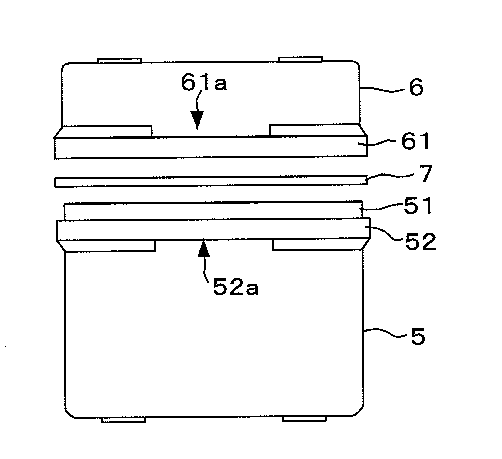
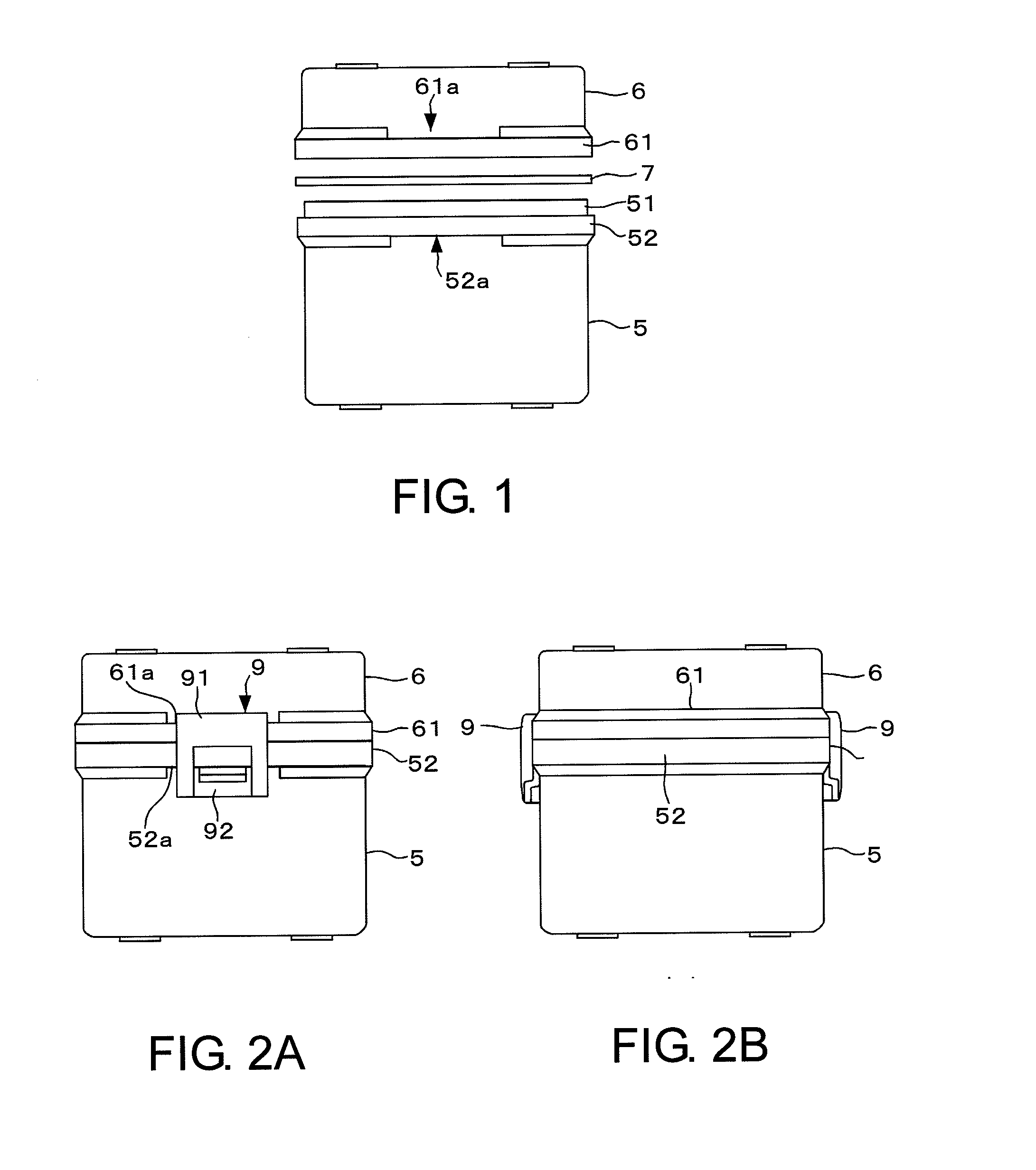
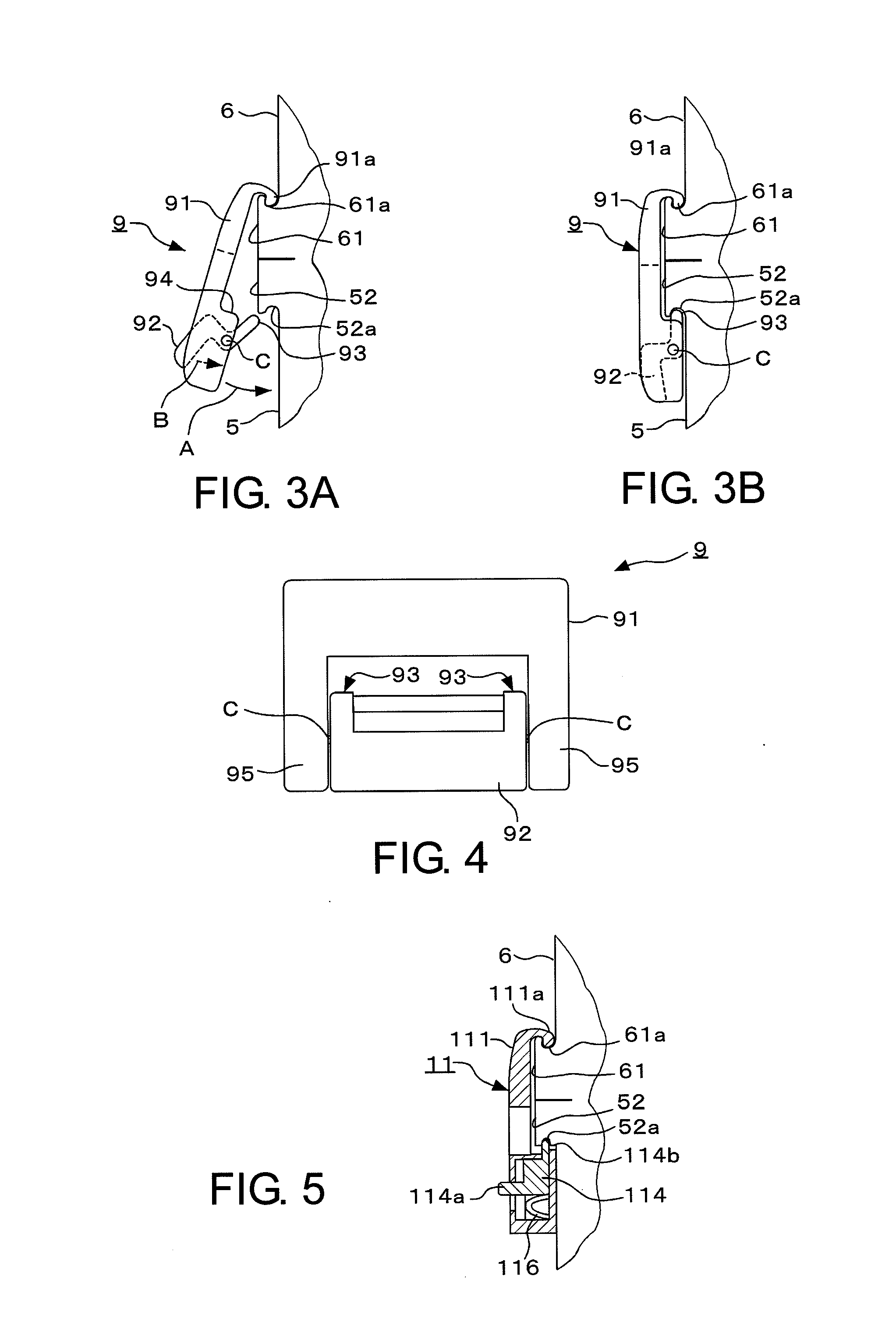
[0064]A plurality of mask blanks, 20 in number, produced as mentioned above were housed in four containers, five blanks in each container. As the containers, the containers according to the embodiment illustrated in FIGS. 1 through 4 were used. The cap member 6 was made of acrylonitrile butadiene styrene (ABS). Each of the container body 5 and the inner case was made of polypropylene. The fixing member 9 was made of ABS. The supporting member 8 fixed to the cap member 6 was made of polybutylene terephthalate. The elastic member 7 was made of polyolefin elastomer. The housing operation was ca...


PUM


Abstract

A mask blank container is adapted to house a mask blank with a resist film. The container comprises a container body 5 for receiving the mask blank; a cap member 6 to be put on the container body; and a fixing member 9 adapted to fix the container body and the cap member to each other when the cap member is put on the container body. The container body and the cap member have fitting portions 51 and 61 made of a resin material and fitted to each other, respectively. The fixing member comprises a first member 91 having an engaging portion 91 a to be engaged with the fitting portion of the cap member, and a second member 92 having an engaging portion 93 to be engaged with the fitting portion of the container body. A distance between the engaging portions of the first and the second members is desired to be variable.

Description

[0001]This application is based upon and claims the benefit of priority from Japanese patent application No. 2008-249337, filed on Sep. 27, 2008, the disclosure of which is incorporated herein in its entirety by reference.TECHNICAL FIELD[0002]This invention relates to a container for housing a mask blank for use in fabrication of a photomask or the like to be used in manufacture of an electronic device and to a method of housing the mask blank.BACKGROUND ART[0003]Following rapid development of the IT (Information Technology) industry, a recent electronic device, in particular, a semiconductor device, a color filter or a TFT (Thin Film Transistor) device for a LCD (Liquid Crystal Display) monitor, or the like, is required to have a finer structure. One of techniques supporting fine process technology for such a finer structure is a lithography technique using a photo mask called a transfer mask. In the lithography technique, a silicon wafer with a resist film is exposed through the t...

Claims


Application Information

Patent Timeline
IPC IPC(8): B65D51/00B65D85/86G03F1/50G03F1/66
CPCG03F1/66H01L21/67383H01L21/67373H01L21/67359H01L21/00
Inventor MIZUKOSHI, YASUHIROHANAOKA, OSAMU
Owner HOYA CORP
Learn More