Radio frequency identification reader having antennas in different directions

a radiation frequency identification and reader technology, applied in the direction of burglar alarm mechanical actuation, burglar alarm by hand-portable object removal, etc., can solve the problems of poor correlation between signal magnitude and distance, poor signal transmission spots, poor signal reception at sites where radiation electric field is present, etc., to achieve excellent signal reception performance, extend the range, and improve the effect of signal reception

Inactive Publication Date: 2010-04-01
MITAC TECH CORP
View PDF9 Cites 28 Cited by
  • Summary
  • Abstract
  • Description
  • Claims
  • Application Information

AI Technical Summary

Benefits of technology

[0008]With the arrangement of signal antennas in different directions in accordance with the present invention, the direction having weak radiation electric field in the antenna field pattern of each signal antenna can be covered by a strong portion of the radiation electric field in the antenna field pattern of another signal antenna, whereby when the plurality of signal antennas is used simultaneously, the radiation electric field of a combined antenna field pattern can have an expanded range and provides a substantial distribution in all directions. When an RFID tag is located in a direction of one of the signal antennas that has a poor performance of signal reception, the RFID reader will be just in a direction of another one of the signal antennas that has an excellent performance of signal reception. Thus, excellent signal transmission and reception can be realized regardless how the RFID tag is moved.
[0009]Since the signal antennas are arranged in different directions, any problems caused due to the included angle between the RFID reader antenna and the RFID tag antenna can be eliminated. In an embodiment of the present invention, all the signal antennas of an RFID reader are set in mutually perpendicular directions, whereby when one of the signal antennas of the RFID reader is orientated orthogonal to the RFID tag antenna, although the performance of signal transmission and reception of the signal antenna that is orthogonal to the RFID tag antenna becomes poor, at least one of the remaining signal antennas of the RFID reader is not orientated orthogonal to the RFID tag antenna and provides better transmission and reception. Thus, due to the mutual compensation among the plurality of signal antennas provided to the RFID reader, the RFID reader is capable to always maintain excellent transmission and reception of signals.

Problems solved by technology

In the known techniques, an RFID reader has an antenna that provides an antenna field pattern having a variable distribution of a radiation electric field in different directions, leading to dead spots of signal transmission and poor reception at sites where the radiation electric field is weak.
In case that an included angle between the antenna of the RFID reader is normal to the antenna of a RFID tag becomes a right angle, it is very likely that no signal transmission or reception is available no matter how close is the RFID tag to the RFID reader and the correlation between signal magnitude and distance becomes poor, making it no longer possible to perform RFID tag location identification through signal magnitude, thereby leading to poor applicability thereof.
Further, in different applications, such as industrial or commercial applications, there may exist various electromagnetic interferences, which cause noises in signal transmission and reception.

Method used


Image

  • Radio frequency identification reader having antennas in different directions
  • Radio frequency identification reader having antennas in different directions
  • Radio frequency identification reader having antennas in different directions

Examples


Embodiment Construction

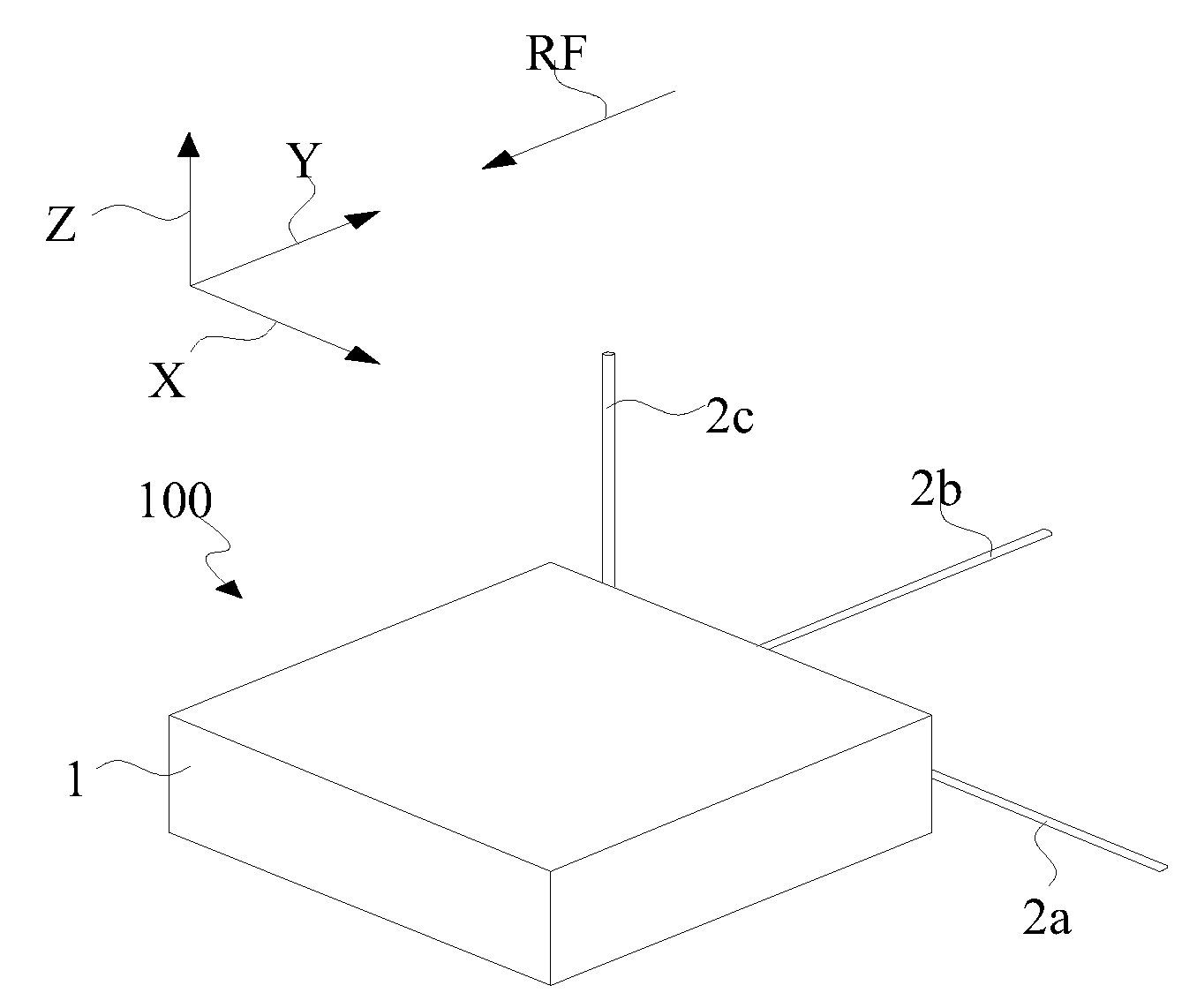
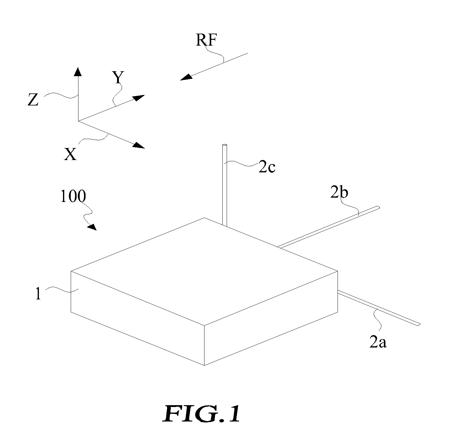
[0018]With reference to the drawings and in particular to FIG. 1, which shows a perspective view of an RFID (Radio Frequency Identification) reader having antennas in different directions constructed in accordance with a first embodiment of the present invention, the RFID reader of the present invention, generally designated at 100, comprises a casing 1, a first signal antenna 2a, a second signal antenna 2b, and a third signal antenna 2c. The first signal antenna 2a, the second signal antenna 2b, and the third signal antenna 2c are arranged in mutually normal directions defined by X-, Y-, and Z-axis in a space and each of the antennas has a predetermined antenna field pattern operating with a carrier wave of a predetermined frequency f. Although the first signal antenna 2a, the second signal antenna 2b, and the third signal antenna 2c are arranged in the directions of X-, Y-, and Z-axis that are normal to each other in the first embodiment of the present invention, they can be arran...


PUM


Abstract

A radio frequency identification (RFID) reader includes a plurality of signal antennas, which are respectively arranged in directions that are not parallel to and co-linear with each other. Each of the signal antennas has a predetermined antenna field pattern and operates with a predetermined carrier wave frequency. A wireless receiver is connected to the signal antennas. A signal conversion unit is connected to the wireless receiver. A frequency generator generates the carrier wave frequency to the signal antenna. A microprocessor is connected to the signal conversion unit and the frequency generator.

Description

FIELD OF THE INVENTION[0001]The present invention relates to a design of radiation frequency identification (RFID) reader, and more particularly to a RFID reader equipped with multiple antennas in different directions.BACKGROUND OF THE INVENTION[0002]A radiation frequency identification (RFID) system comprises a RFID reader and a RFID tag. Data contained in the RFID tag is transmitted via radio frequency signals to the RFID reader. Power is transmitted, also via the radio frequency signals, to the RFID tag so that the RFID tag can operate without a built-in battery-based power source.[0003]The reliability of an RFID system is affected by antennas of the RFID tag and the RFID reader. An electrical current flowing through the antenna generates an electromagnetic pulse that radiates outward with the speed of light. A direction of the radiation electric field (referred to as direction of polarization) is normal to the propagation direction of wave front of the electromagnetic wave. The ...

Claims


Application Information

Patent Timeline
Patent Type & Authority Applications(United States)
IPC IPC(8): H04Q5/22
CPCH04Q2213/13003G06K7/10346
Inventor PERNG, SHIN-YAOLEE, TA-YUNGYU, CHIA-CHINSHIAU, JUN-TING
Owner MITAC TECH CORP
Why Eureka
Try Eureka