X-ray ct system to generate tomographic phase contrast or dark field exposures

a tomographic phase contrast and dark field technology, applied in the field of x-ray computed tomography (ct) system, can solve the problems of large fan angle arrangement of grating/detector modules, and achieve the effect of improving measurements

a tomographic phase contrast and dark field technology, applied in the field of x-ray computed tomography (ct) system, can solve the problems of large fan angle arrangement of grating/detector modules, and achieve the effect of improving measurements

US20100080341A1Inactive Publication Date: 2010-04-01SIEMENS HEATHCARE GMBH +1

Image

  • X-ray ct system to generate tomographic phase contrast or dark field exposures
  • X-ray ct system to generate tomographic phase contrast or dark field exposures
  • X-ray ct system to generate tomographic phase contrast or dark field exposures

Examples


Embodiment Construction

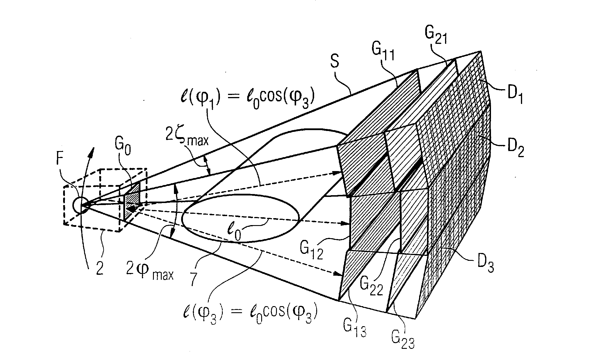
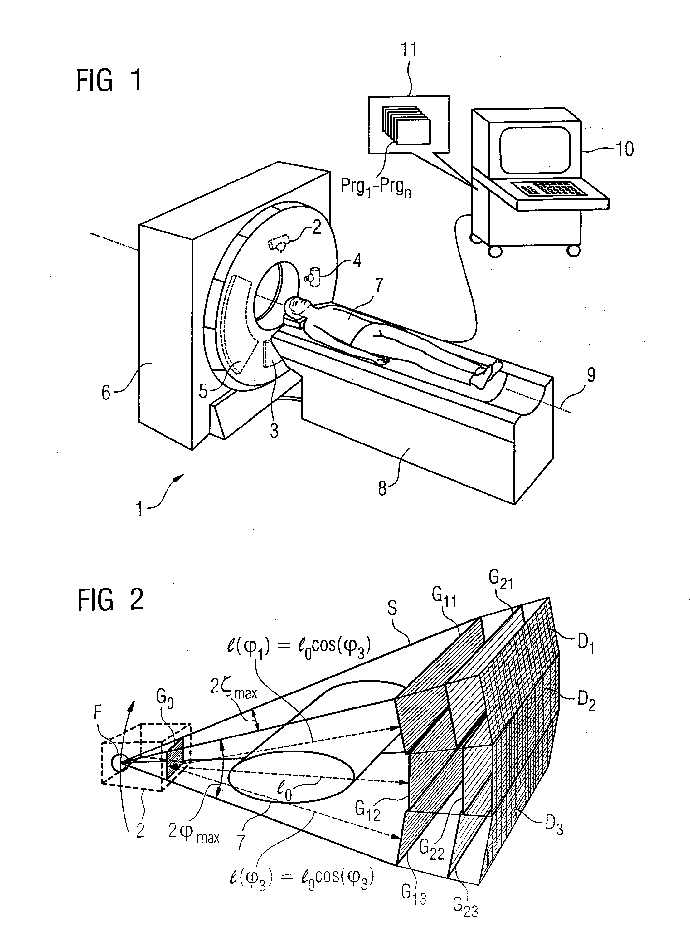
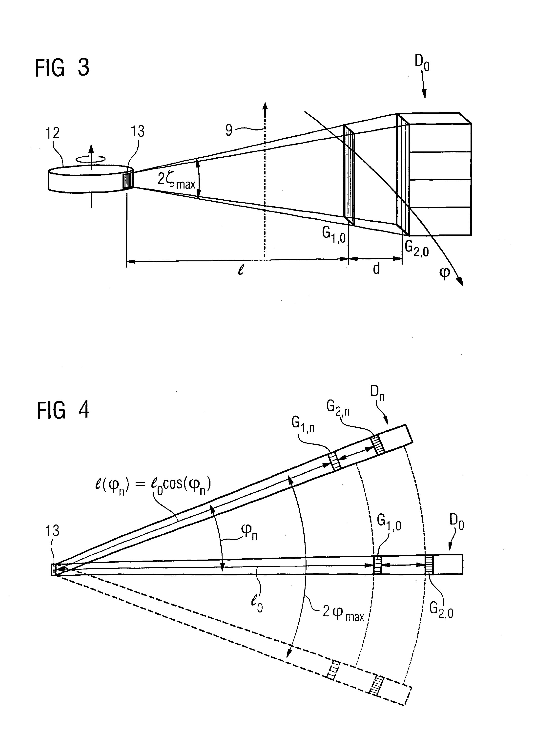
[0042]In the following the invention is described in detail with the figures, wherein only the features necessary to understand the invention are shown. The following reference characters and symbols are hereby used: 1: x-ray CT system; 2: x-ray source; 3: detector; 4: x-ray source; 5: detector; 6: gantry housing; 7: patient; 8: patient bed; 9: system axis; 10: control and computing system; 11: memory; 12: rotating anode; 13: source-side grating structure; 14: depressions; 15: second material; 16: electron emitters; 17: magnetic field; d: distance from the phase grating G1 to the analysis grating G2 in the fan beam geometry; d≡: distance form the phase grating G1 to the analysis grating G2 under parallel geometry; D: detector; e−: electrons; F: focus / focal spot; G0: source grating; G1, G1,i: phase grating; G2, G2,i: analysis grating; hi: web height of the phase grating G1 in the beam direction; Imed: median radiation intensity; Iamp: amplitude; Iamp: amplitude; I: distance from the ...


PUM


Abstract

An x-ray CT system that generates tomographic phase contrast or dark field exposures, has at least one grating interferometer with three grating structures arranged in series in the radiation direction, with a modular design of the second and third grating structures. The distance between the first grating structure of the x-ray source and the second grating structure (fashioned as a phase grating) of the respective grating / detector modules is adapted, depending on the fan angle, corresponding to a period of the grating structure of the x-ray source projected onto the grating detector module at a respective fan angle (φi).

Description

BACKGROUND OF THE INVENTION[0001]1. Field of the Invention[0002]The invention concerns an x-ray computed tomography (CT) system of the type having a source / detector system to generate tomographic phase contrast or dark field exposures, the source / detector system being arranged on a gantry that can rotate around a system axis.[0003]2. Description of the Prior Art[0004]An x-ray CT system for generating tomographic phase contrast or dark field exposures is known that has a source / detector system mounted on a gantry for rotation around a system axis. The source / detector system of this known x-ray CT system has an x-ray source and a detector arrangement. The x-ray source has a grating structure that emits bands of emission maxima and emission minima of a generated x-ray radiation with a grating period, the bands are arranged like a grating, so a beam fan of x-rays expanding in two planes arises with a maximum fan angle in the rotation plane of the gantry and a Z-angle perpendicular to th...

Claims


Application Information

Patent Timeline
01 Apr 2010
Publication
US20100080341A1
IPC
H05G1/60
CPC
A61B6/032; A61B6/08; A61B6/4291; A61B6/484; G21K2207/005; A61B6/4233; A61B6/4435
Inventors
POPESCU, STEFAN; DAVID, CHRISTIAN