
Scalloped surface turbine stage with trailing edge ridges

a surface turbine and trailing edge technology, applied in the field of turbines, can solve the problems of unsatisfactory reduction of overall turbine efficiency, turbine pressure loss, horseshoe vortex, etc., and achieve the effects of improving efficiency and thermal loading, reducing horseshoe and secondary flow vortex affecting, and increasing aerodynamic loading

Active Publication Date: 2010-04-01
GENERAL ELECTRIC CO
View PDF6 Cites 88 Cited by
  • Summary
  • Abstract
  • Description
  • Claims
  • Application Information

AI Technical Summary

Benefits of technology

[0017]Accordingly, it is desired to provide an improved turbine stage for reducing horseshoe and secondary flow vortex affects, as well as increasing aerodynamic lo

Problems solved by technology

Undesirable pressure losses in the combustion gas flowpaths therefore correspond with undesirable reduction in overall turbine efficiency.
One common source of turbine pressure losses is the formation of horseshoe vortices generated as the combustion gases are split in their travel around the airfoil leading edges.
The interaction of the pressure and suction side vortices occurs near the midspan region of the airfoils and creates total pressure loss and a corresponding reduction in turbine efficiency.
These vortices may increase undesirable heating of the endwalls.
Since the horseshoe vortices are formed at the junctions of the turbine rotor blades and their integral root platforms, as well as at the junctions of nozzle stator vanes and their outer and inner bands, corresponding losses in turbine efficiency are created, as well as leading to the possible additional heating of the corresponding endwall components.
Similarly, cross-passage gradients between the pressure and suction side of the blade give rise to secondary flow structures and vortices that alter the desired aerodynamics of the blade, giving rise to losses in turbine efficiency as well as possible heating of the endwalls and even the blade.
The interaction of these secondary flow structures are responsible for aerodynamic losses at the trailing edge, especially near the turbine blade endwalls.
Further, these secondary flow structures result in high heat concentrations in the area where the turbine blade join the blade endwall structure.
Because of these high heat concentrations coupled with the high structural loads experienced at the trailing edges, aerodynamic profiling options of the blade trailing edges are limited.

Method used


Image

  • Scalloped surface turbine stage with trailing edge ridges
  • Scalloped surface turbine stage with trailing edge ridges
  • Scalloped surface turbine stage with trailing edge ridges

Examples


Embodiment Construction

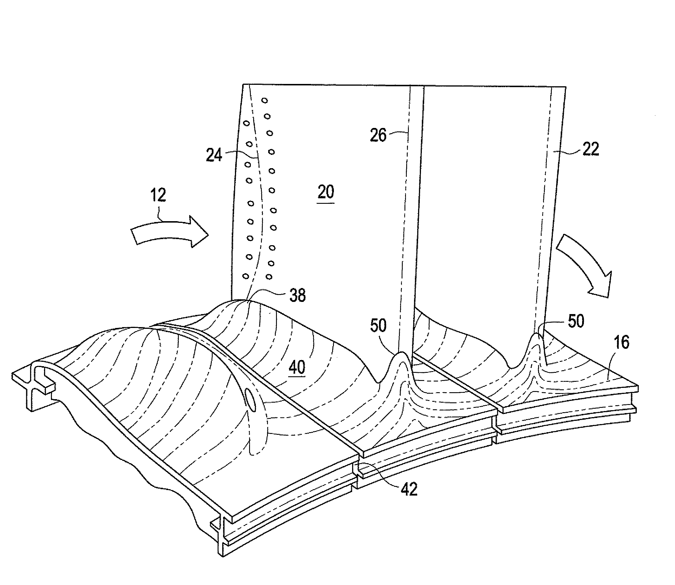
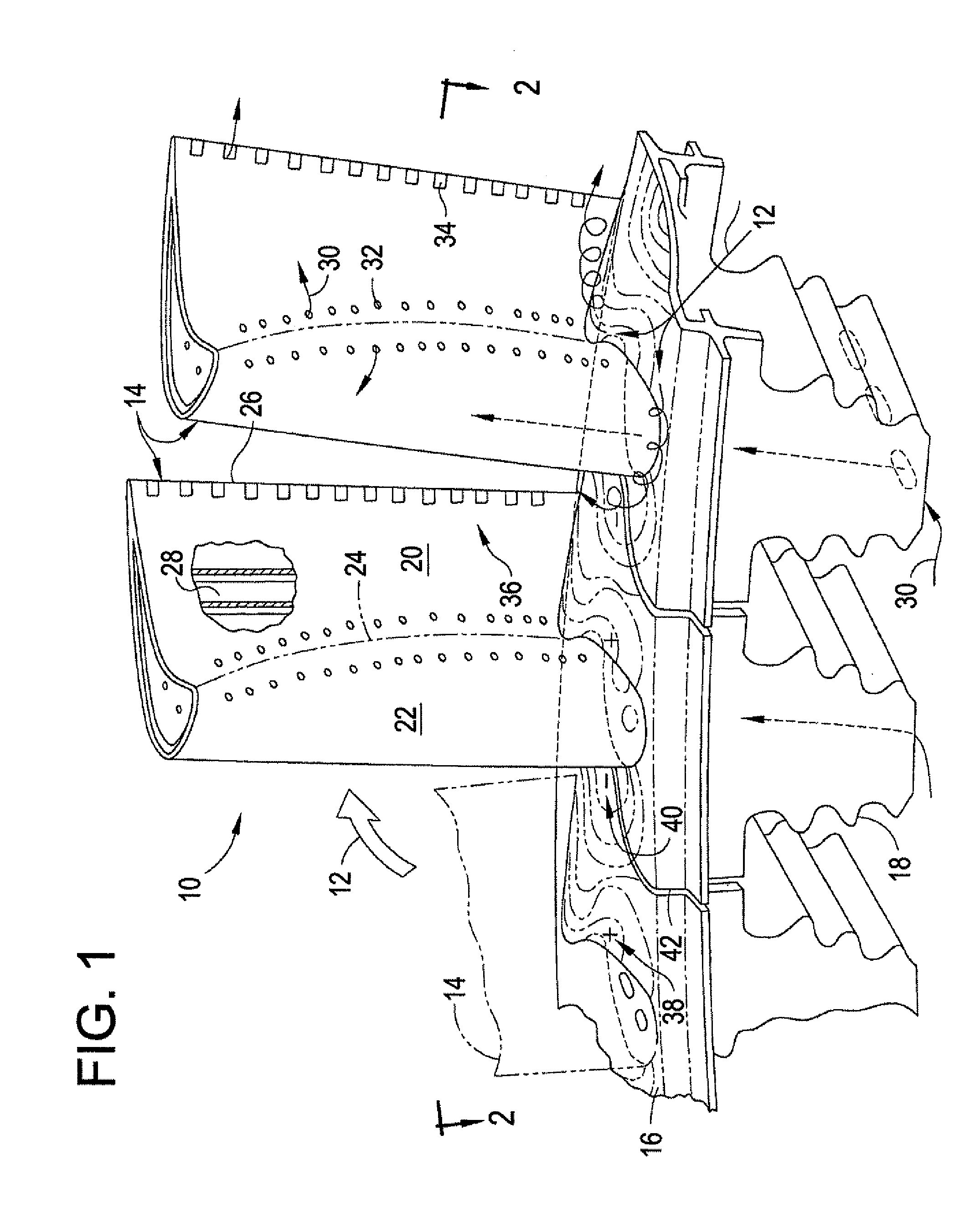
[0027]Illustrated in FIG. 1 are two exemplary first stage turbine rotor blades 10 which circumferentially adjoin each other in a full row thereof in a corresponding turbine stage of a gas turbine engine. As indicated above, combustion gases 12 are formed in a combustor (not shown) and discharged in the axial downstream direction through the row of turbine blades 10 which extract energy therefrom for powering a supporting rotor disk (not shown) on which the blades are mounted.

[0028]The turbine stage includes a complete row of the blades, with each blade having a corresponding airfoil 14 joined at a root end to a corresponding radially inner endwall or platform 16. Each platform may in turn be joined to a corresponding axial-entry dovetail 18 conventionally configured for supporting the corresponding turbine blade in the perimeter of the rotor disk.

[0029]Each airfoil includes a generally concave pressure side 20 and a circumferentially or laterally opposite, generally convex suction s...


PUM


Abstract

An engine stage includes a row of airfoils joined to corresponding platforms to define flow passages therebetween. Each airfoil includes opposite pressure and suction sides and extends in chord between opposite leading and trailing edges. Extending from a surface of the platforms is a trailing edge ridge structure which adjoins the pressure sides, suction sides, and trailing edges of the airfoils with their respective platforms.

Description

BACKGROUND OF THE INVENTION[0001]The present invention relates generally to gas turbine engines, any turbomachinery and, more specifically, to turbines therein.[0002]In a gas turbine engine air is pressurized in a compressor and mixed with fuel in a combustor for generating hot combustion gases. Turbine stages extract energy from the combustion gases to power the compressor, while also powering an upstream fan in a turbofan aircraft engine application, or powering an external drive shaft for marine and industrial applications.[0003]A high pressure turbine (HPT) immediately follows the combustor and includes a stationary turbine nozzle which discharges combustion gases into a row of rotating first stage turbine rotor blades extending radially outwardly from a supporting rotor disk. The HPT may include one or more stages of rotor blades and corresponding turbine nozzles.[0004]Following the HPT is a low pressure turbine (LPT) which typically includes multiple stages of rotor blades and...

Claims


Application Information

Patent Timeline
IPC IPC(8): F01D5/14
CPCF01D5/143F01D9/04F05D2270/17Y02T50/673F05D2250/20F05D2240/301F05D2240/80F05D2260/231Y02T50/675Y02T50/60
Inventor GUPTA, ANURAGBARR, BRIAN CHANDLERKIRTKEY, KEVIN RICHARDTAM, ANNA
Owner GENERAL ELECTRIC CO
Features
  • Generate Ideas
  • Intellectual Property
  • Life Sciences
  • Materials
  • Tech Scout
  • Unparalleled Data Quality
  • Higher Quality Content
  • 60% Fewer Hallucinations
Learn More