

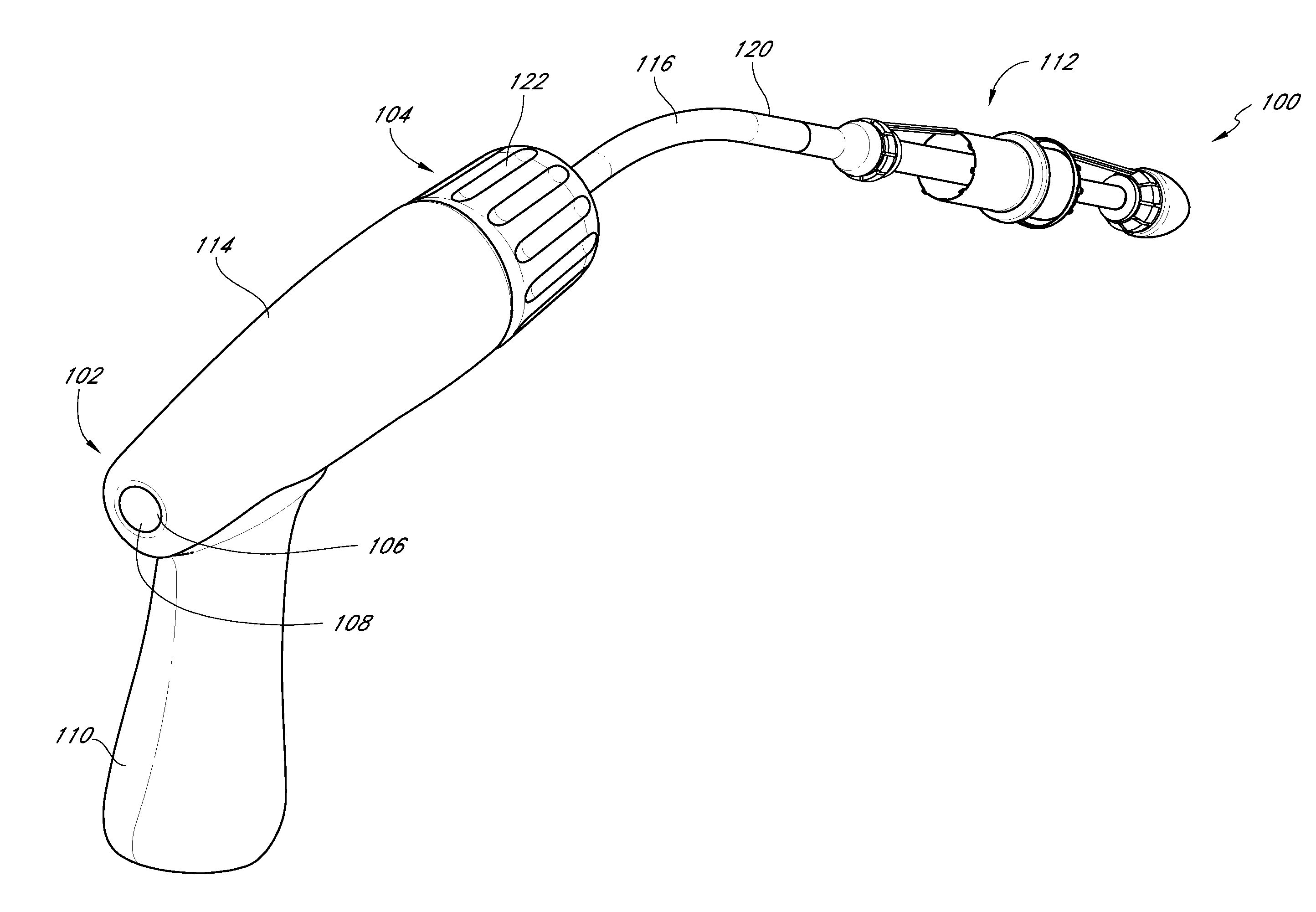
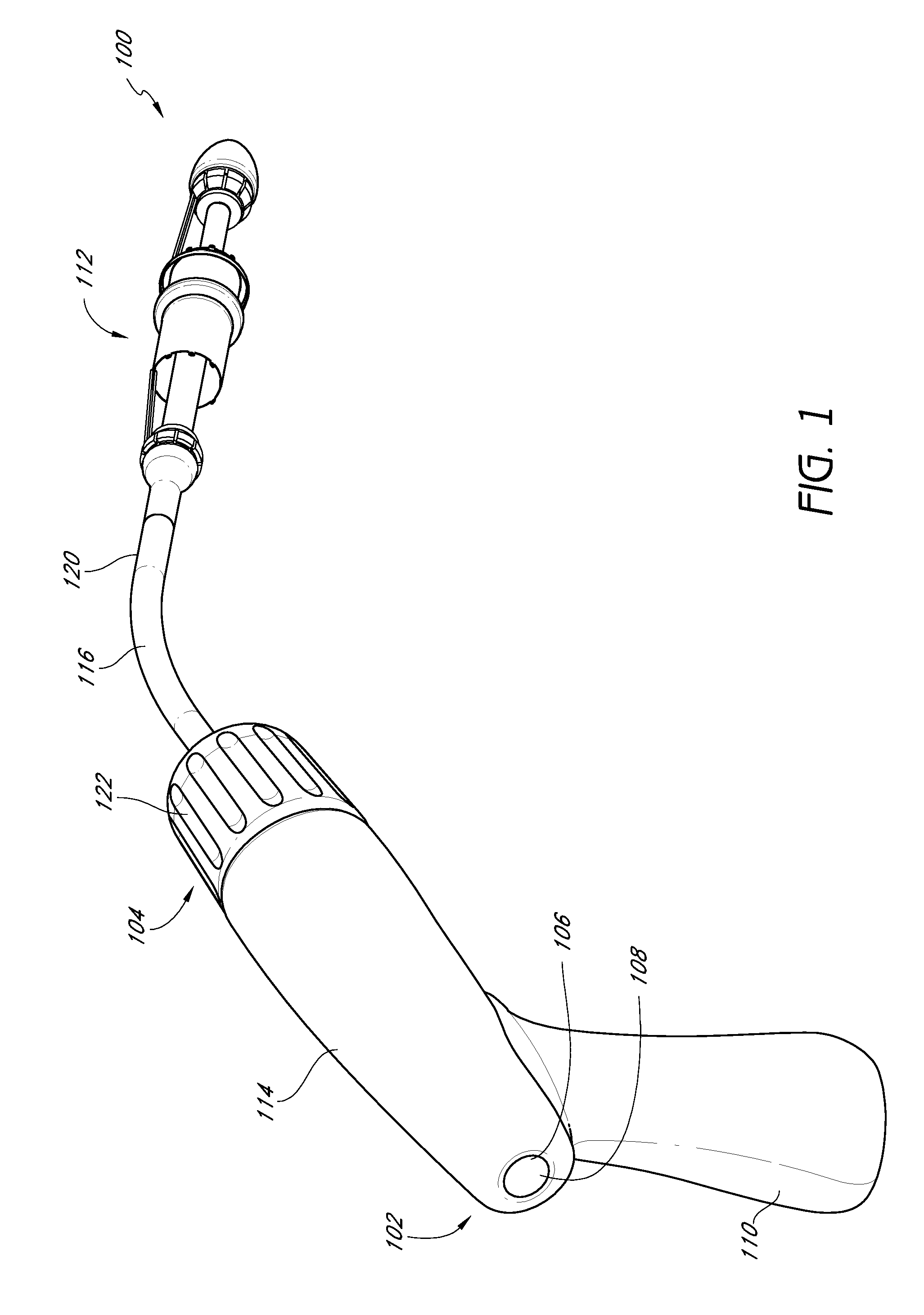
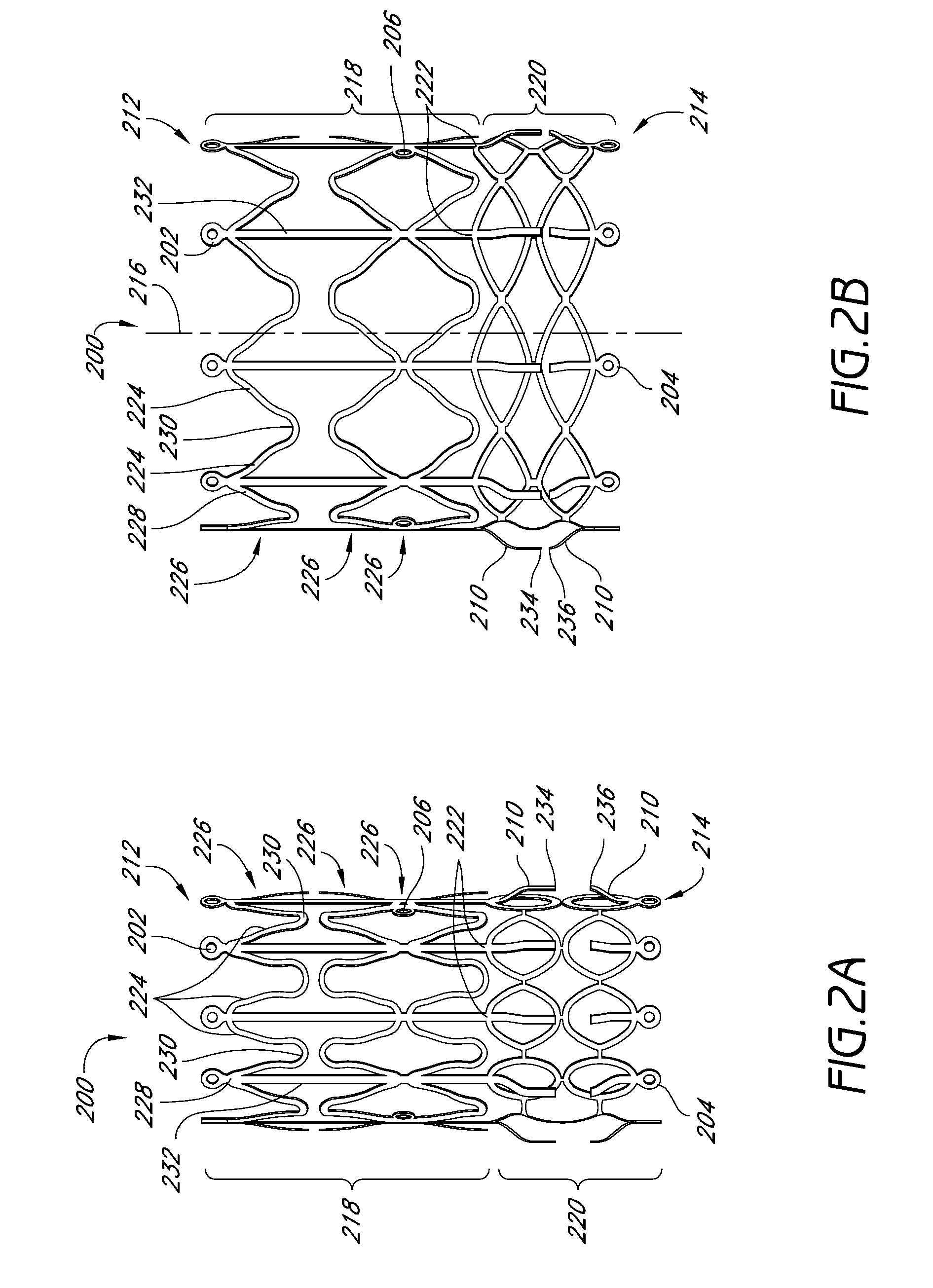
Delivery system for vascular implant
a delivery system and vascular technology, applied in the field of medical implant insertion delivery systems, can solve the problems of inability to reposition the replacement valve after it is fully deployed, no way to reduce the diameter of the heart valve frame, and the inability to collapse to adjust, reposition, or remove the implan
- Summary
- Abstract
- Description
- Claims
- Application Information
AI Technical Summary
Benefits of technology
Problems solved by technology
Method used
Image

Examples
Embodiment Construction
[0051]The associated drawings and specification discuss aspects and features of the present invention in the context of several different embodiments of implant delivery devices and methods that are configured for use in the vasculature of a patient. Discussing these features in connection with heart valve implants employing stents provides for clarity and consistency in presenting these inventive features and concepts. However, it is to be understood that the features and concepts discussed herein can be applied to products other than stented heart valve implant. For example, the controlled positioning, deployment, retraction, and repositioning features described herein can be applied to medical implants for use elsewhere in the body, such as within the coronary arteries, the digestive tract, or the like.
[0052]In fact, the principles discussed herein can be used in any application that would benefit from a prosthesis delivery device having repositioning capability and / or a reduced ...
PUM
 Abstract
Description
Claims
Application Information