Information recording medium and optical recording/reproducing apparatus

a technology of information recording and optical recording, which is applied in the direction of recording signal processing, instruments, zoned data area, etc., can solve the problems of difficult to achieve reproduction without adjusting the reproduction power, the management information cannot be reproduced by conventional optical recording methods, and the conventional technology cannot reproduce the management information. achieve the effect of maintaining downward compatibility, increasing accuracy, and maintaining downward compatibility of the apparatus

Inactive Publication Date: 2010-04-01
HITACHI CONSUMER ELECTRONICS CORP
View PDF15 Cites 26 Cited by
  • Summary
  • Abstract
  • Description
  • Claims
  • Application Information

AI Technical Summary

Benefits of technology

[0021]As the management information is formed in the normal resolution region, the reproduction power for an initial disk read can be preset with reference to a normal resolution method. It means that the disk has no risk of being damaged by excessive reproduction power of laser irradiation. It is therefore possible to provide an optical disk or optical disk drive that is capable of reproducing the management information without fail while maintaining downward compatibility.
[0022]As the management information, positional information (e.g., address information and region information), which indicates where on an optical disk the information recorded by a super resolution method is positioned, is recorded in the normal resolution region. If necessary, a rec

Problems solved by technology

However, if the management information is recorded in the super resolution region, the management information cannot be reproduced by reproduction methods based on conventional optical disk technologies.
If the track intervals are smaller th

Method used


Image

  • Information recording medium and optical recording/reproducing apparatus
  • Information recording medium and optical recording/reproducing apparatus
  • Information recording medium and optical recording/reproducing apparatus

Examples


first embodiment

[0065]An exemplary configuration according to a first embodiment of the present invention will now be described. The first embodiment uses an optical disk that records optical disk management information in a normal resolution region and user information in a super resolution region. In other words, the first embodiment uses a read-only optical disk (ROM) constructed so that the normal resolution region and super resolution region coexist in the same recording layer.

[0066]FIG. 2A is a top view illustrating a recording layer of the optical disk (medium) according to the present embodiment. FIG. 2B shows specifications for the optical disk recording layer, which is shown in FIG. 2A. The optical disk shown in FIGS. 2A and 2B is a 12 cm diameter ROM type medium having a single information recording layer. The information recording layer includes an information region, which is a region spanning between a radius of 20 mm and a radius of 56 mm.

[0067]Four areas are formed in the recording ...

second embodiment

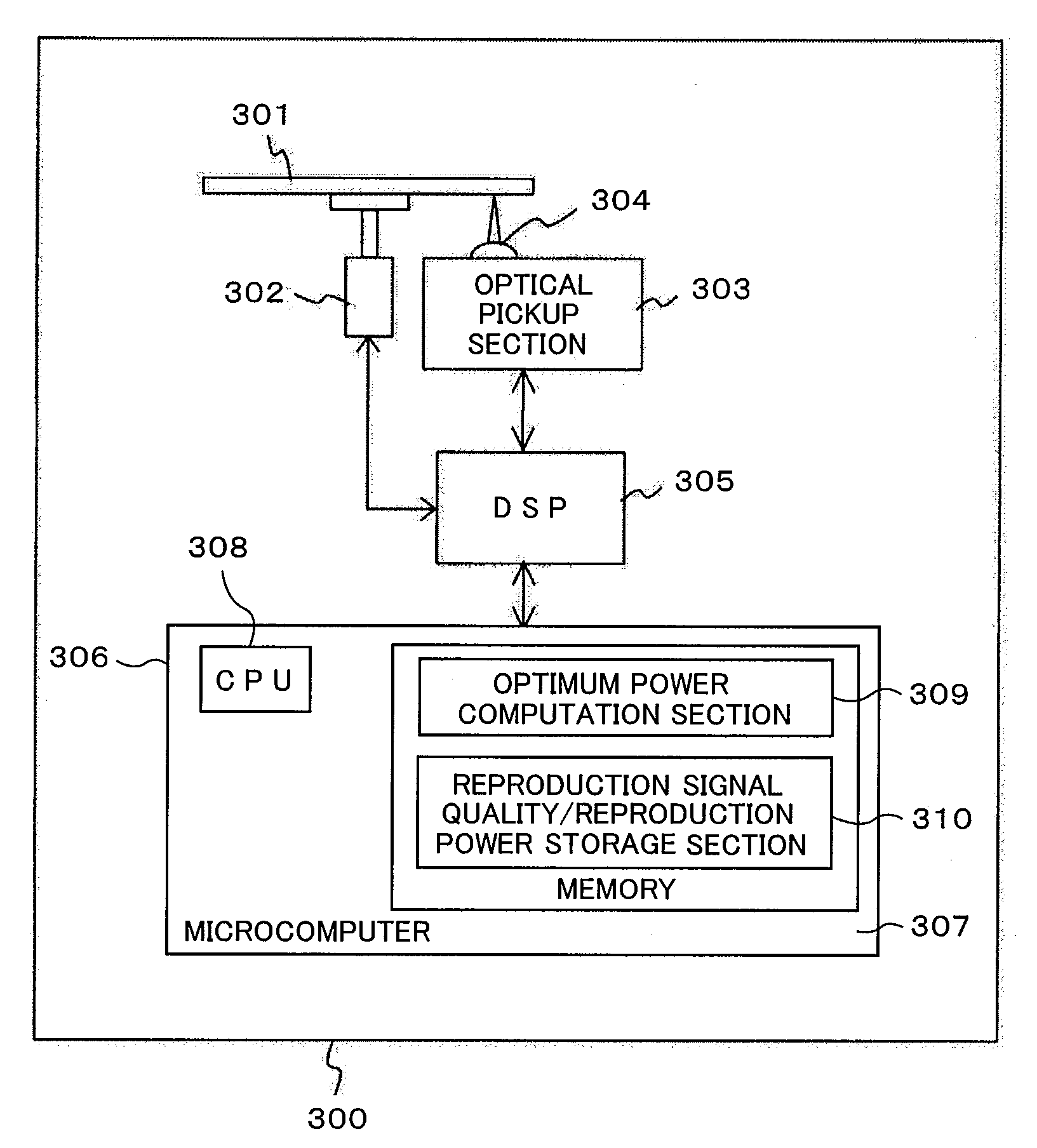
[0086]A second embodiment of the present invention will now be described. Although the second embodiment has the same structure as the first embodiment, an exemplary configuration of the second embodiment will be described below on the assumption that a recommended reproduction power value for the super resolution region is stored in the management region of an employed optical disk. The optical disk according to the second embodiment will not be described here because it has exactly the same structure as the optical disk shown in FIGS. 2A and 2B. The optical disk drive according to the second embodiment has the same structure as the optical disk drive shown in FIG. 3, but does not incorporate software programs such as the “optimum power computation section” and “reproduction signal quality / reproduction power storage section”.

[0087]FIG. 7 is a flowchart illustrating an operation that the optical disk drive according to the present embodiment performs during reproduction. Steps 701 a...

third embodiment

[0091]The optical disk described in connection with the first and second embodiments is formatted so that the normal resolution region and super resolution region coexist in the same recording layer. However, the optical disk that uses the super resolution method to achieve recording and reproduction may have various configurations other than those described in connection with the first and second embodiments. A third embodiment of the present invention will be described below in connection with super resolution optical disks having different formats.

(1) First Format

[0092]The configuration of an optical disk of a first format will now be described with reference to FIGS. 8A to 8C. FIG. 8A is a schematic diagram illustrating the positional relationship between data regions of the optical disk of the first format. The optical disk shown in FIG. 8A is a ROM type medium having two information recording layers. The first layer of the optical disk includes a normal resolution region, whic...


PUM


Abstract

When a super resolution technology for optical disks is used in a situation where optical disk management information is formed with a signal that cannot be reproduced by a reproduction method based on a conventional optical disk technology, optical disk drives cannot make recording adjustments and/or reproduction adjustments.
An optical disk drive uses an optical disk that forms a management information signal with pits not smaller in size than optical resolution and can be read by a reproduction method based on a conventional optical disk technology. When the optical disk drive records information onto or reproduces information from the optical disk having the super resolution region, it is possible to make proper recording adjustments or reproduction adjustments and perform a proper recording operation or reproducing operation in an optical disk's information region for user information recording or reproduction.

Description

CLAIM OF PRIORITY[0001]The present application claims priority from Japanese patent application JP2008-252982 filed on Sep. 30, 2008, the content of which is hereby incorporated by reference into this application.BACKGROUND OF THE INVENTION[0002]The present invention relates to an information recording medium and an optical recording / reproducing apparatus, and more particularly to an information recording medium and optical recording / reproducing apparatus for use with a super resolution technology that reproduces pits smaller in size than optical resolution by using heat generated upon laser irradiation.[0003]Optical disks are widely used as information recording media. When an optical disk is used to record a signal or reproduce a recorded signal, an information recording layer of the optical disk is irradiated with laser light that is focused by an objective lens. The size of the resulting focused light spot is expressed by λ / NA where λ is the wavelength of the laser light and NA ...

Claims


Application Information

Patent Timeline
IPC IPC(8): G11B17/028G11B7/24
CPCG11B7/00736G11B7/0079G11B7/0953G11B7/1263G11B2220/2595G11B7/24G11B2007/0013G11B20/1217G11B2220/235G11B7/1267
Inventor ETO, SOICHIROSHINTANI, TOSHIMICHIMINEMURA, HIROYUKI
Owner HITACHI CONSUMER ELECTRONICS CORP
Why Eureka
Try Eureka