
Apparatus and Method for Optimizing Exhaust Temperature Control in a Vehicle During Particulate Filter Regneration

a technology of exhaust gas and temperature control, applied in the direction of electrical control, machine/engine, electric control of exhaust gas, etc., can solve the problems of increasing the temperature of exhaust gas and the same temperature control method being less than optimal, so as to reduce the occurrence and/or severity of temperature overshoot or oscillation, the effect of large thermal mass

Active Publication Date: 2010-04-08
GM GLOBAL TECH OPERATIONS LLC
View PDF6 Cites 14 Cited by
  • Summary
  • Abstract
  • Description
  • Claims
  • Application Information

AI Technical Summary

Benefits of technology

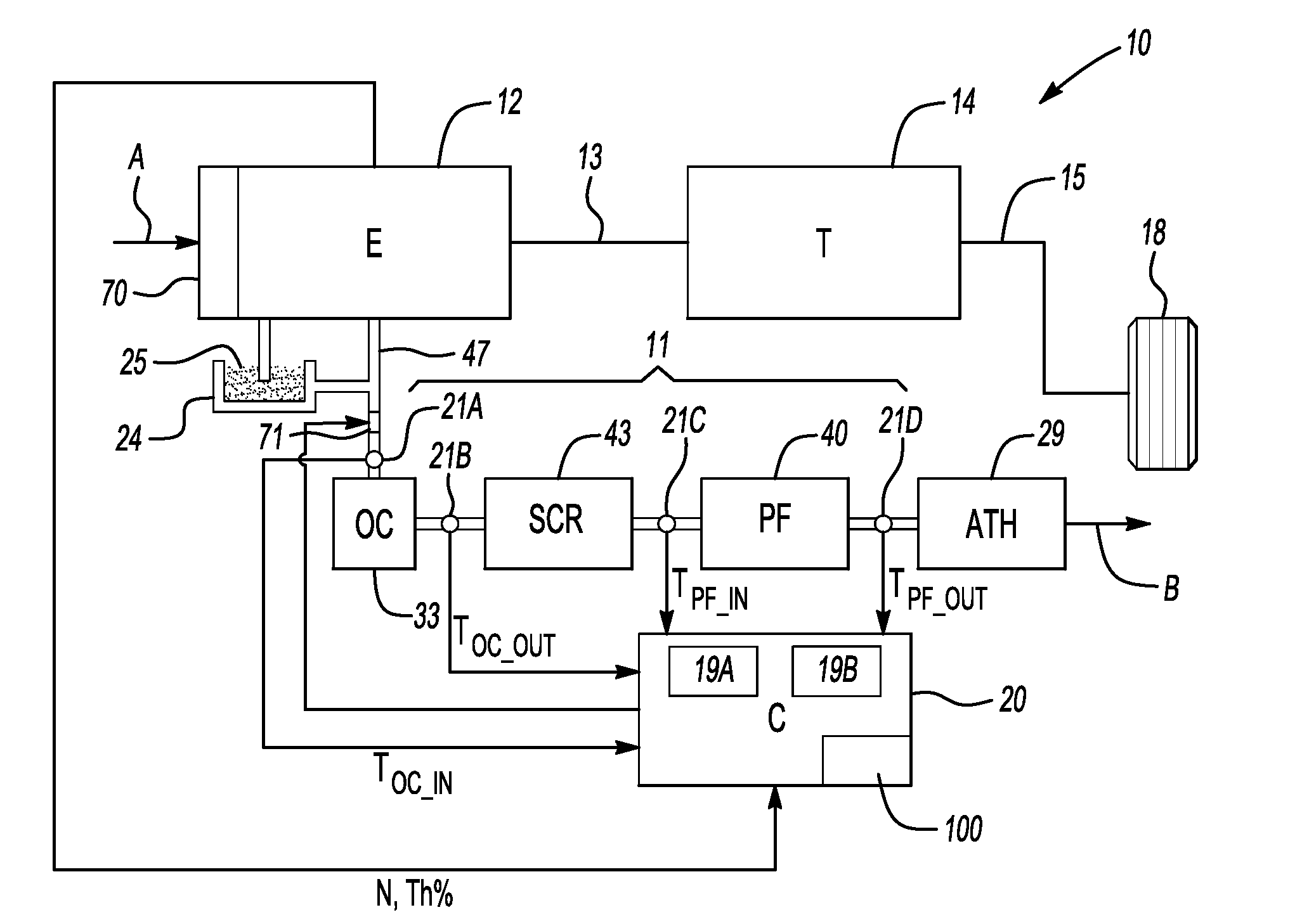
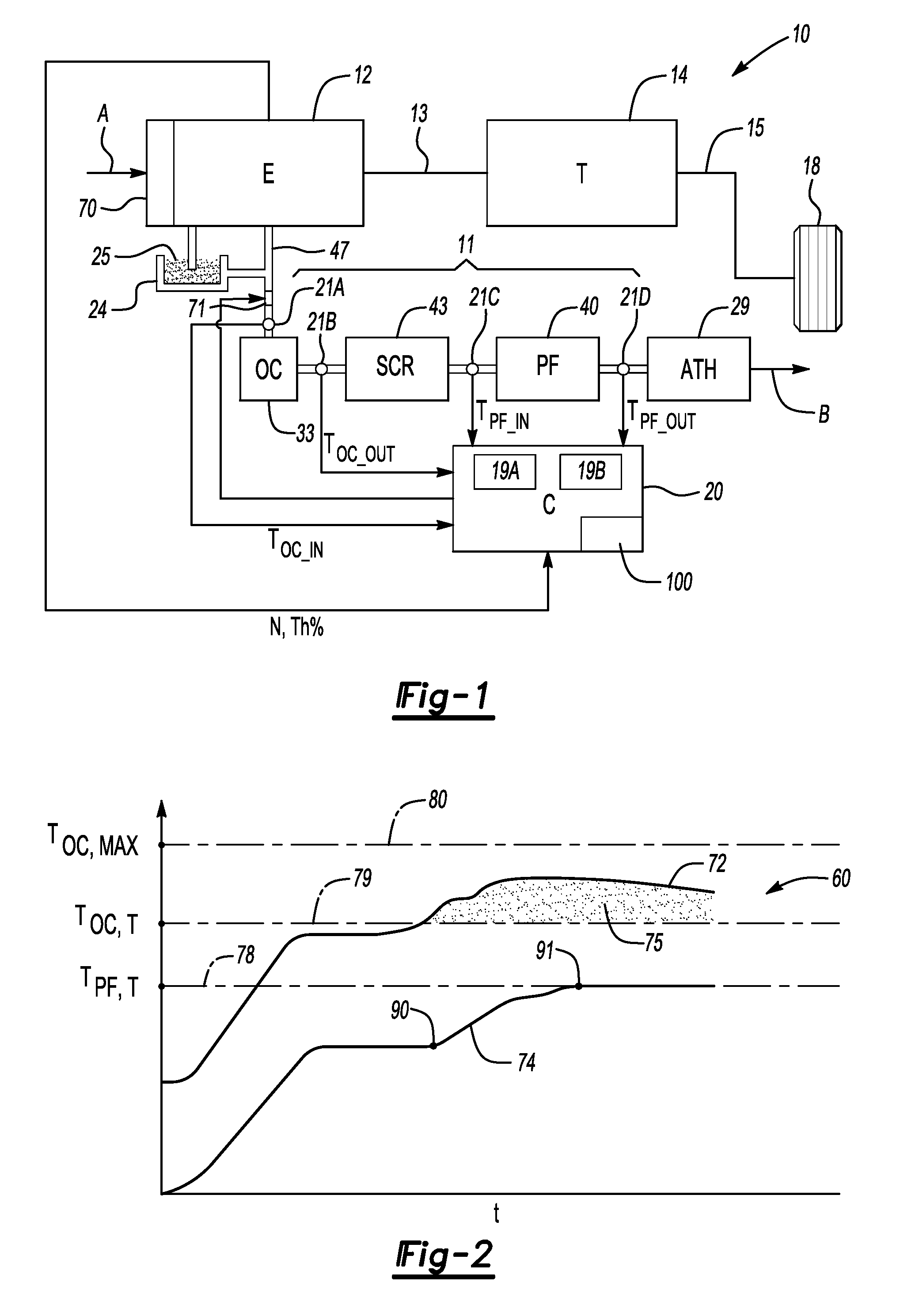
[0005]Accordingly, a method and an apparatus are provided for optimizing the temperature control of an exhaust gas or exhaust stream of a vehicle engine. The apparatus controls the temperature of the exhaust gas within the exhaust system during regeneration of the particulate filter (PF). The apparatus includes the PF itself, an oxidation catalyst (OC), and a selective catalytic reduction catalyst or SCR located between the OC and the PF within the exhaust stream. The SCR provides the relatively large thermal mass mentioned above. The PF can be selectively regenerated using the OC, with the SCR being adapted to convert nitrogen oxides or NOx gasses into relatively inert or harmless byproducts. Using the method and system of the invention, the occurrence and / or severity of any temperature overshoot or oscillation is minimized. Likewise, any after-treatment hardware, i.e., hardware or other devices which capture and / or treat other gasses or byproducts downstream of the PF are sufficiently protected from such a temperature overshoot.
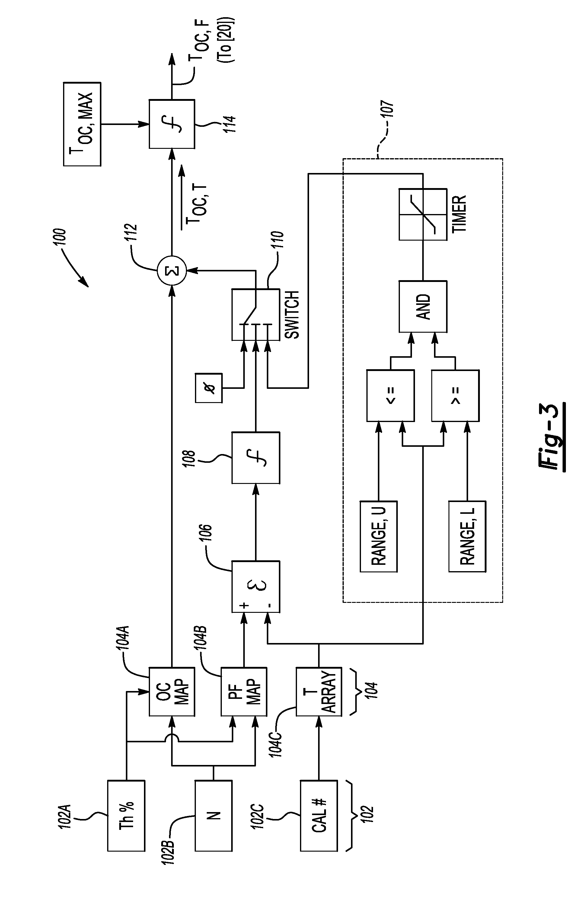
[0007]Two feedback control loops are used to control the temperature of the PF inlet. The primary loop control variable is the outlet temperature of the OC. This particular loop controls the outlet temperature of the OC to a predetermined or calibrated first temperature “set point” by varying the concentration of the hydrocarbons in the exhaust gas, for example by using in-cylinder means, an external hydrocarbon dosing device, or other suitable methods. The secondary control loop utilizes an additional temperature sensor positioned at the outlet of the SCR, or alternately at the inlet of the PF. The secondary control loop utilizes a second temperature set point, which can be subtracted from a measured PF inlet temperature to thereby calculate an error value or term. The error term can then be filtered or processed in any manner that increases system stability, before being added to the first temperature set point. Temperature control at the inlet of the PF is thus optimized while protecting against temperature overshoot.

Problems solved by technology

This process is exothermic in nature, which results in an increased exhaust gas temperature.
However, the same method of temperature control can be less than optimal under certain circumstances, such as when a relatively large thermal mass is present between the OC outlet and the PF inlet.

Method used


Image

  • Apparatus and Method for Optimizing Exhaust Temperature Control in a Vehicle During Particulate Filter Regneration
  • Apparatus and Method for Optimizing Exhaust Temperature Control in a Vehicle During Particulate Filter Regneration
  • Apparatus and Method for Optimizing Exhaust Temperature Control in a Vehicle During Particulate Filter Regneration

Examples


Embodiment Construction

[0013]Referring to the drawings wherein like reference numbers represent like components throughout the several figures, and beginning with FIG. 1, a vehicle 10 includes an engine (E) 12 and a transmission (T) 14. The engine 12 is configured as a conventional internal combustion engine, and therefore is operable for combusting a supply of fuel 25 drawn from a sump or a tank 24. The fuel 25 can be diesel or gasoline depending upon the configuration of the engine 12. The engine 12 has a governor or a throttle 70 operable for admitting a predetermined amount or percentage of the fuel 25 and air (arrow A1) as needed into the engine 12 depending on the position of the throttle 70, as will be understood by those of ordinary skill in the art. Combustion of the fuel 25 generates exhaust (arrow B), which is subsequently discharged through an exhaust manifold or a pipe 47 into an exhaust system 11. Energy released by the combustion of the fuel 25 produces a rotational force or torque on an in...


PUM


Abstract

A method controls an exhaust gas temperature from a vehicle engine during regeneration of particulate filter (PF) in a vehicle having an oxidation catalyst (OC) and a selective catalytic reduction catalyst (SCR). The method ensures that a final OC temperature does not exceed a maximum of the target OC outlet temperature and a calibrated maximum OC outlet temperature. An apparatus for controlling a temperature of the exhaust gas includes sensors for measuring a temperature within the exhaust system and a controller having an algorithm, an OC temperature lookup table, and a PF temperature lookup table. The algorithm calculates a target OC outlet temperature using the lookup tables and a delayed error value that compensates for a thermal mass of the SCR. Actual OC outlet temperature is limited during regeneration of the PF to the lesser of the target OC outlet temperature and a calibrated maximum OC outlet temperature.

Description

TECHNICAL FIELD[0001]The present invention relates to a system and a method for controlling the temperature of an exhaust gas in a vehicle during regeneration of a particulate filter.BACKGROUND OF THE INVENTION[0002]In a vehicle powered by an internal combustion engine of a type known in the art, a particulate filter can be positioned within the vehicle exhaust system to remove particulates before the particulate matter can be exhausted into the atmosphere. Such a particulate filter can be relatively efficient at capturing and retaining microscopic particles of soot, ash, sulfates, metallic particles, and / or any other particulate matter that is commonly generated as a byproduct of the fuel combustion process. While diesel engines most commonly employ such a filter, known widely as a diesel particulate filter or DPF, certain gasoline engine designs such as direct injection or DI engines can also utilize a similar particulate filter. A highly efficient particulate filter, regardless o...

Claims


Application Information

Patent Timeline
IPC IPC(8): F01N9/00
CPCF01N3/0231F01N13/009F01N3/2066F01N9/00F01N2900/1602F02D41/025F02D41/029F02D41/1441F02D41/1446F02D2041/1431F02D2200/0802Y02T10/26Y02T10/47Y02T10/24F01N3/106Y02T10/12Y02T10/40Y02A50/20
Inventor MULLINS, JASON DANIELLAROSE, JR., THOMASPERRIN, JAMES M.JASINKIEWICZ, PAUL
Owner GM GLOBAL TECH OPERATIONS LLC
Learn More