
Devices and Methods for Target Molecule Characterization

a technology of target molecule and device, applied in the field of systems, devices and methods for identifying biopolymers, can solve the problems of limiting the length of extensions, difficult to retrieve complexity, and the complexity of the chemistry required to do so

Active Publication Date: 2010-04-08
ARIZONA STATE UNIVERSITY
View PDF13 Cites 152 Cited by
  • Summary
  • Abstract
  • Description
  • Claims
  • Application Information

AI Technical Summary

Benefits of technology

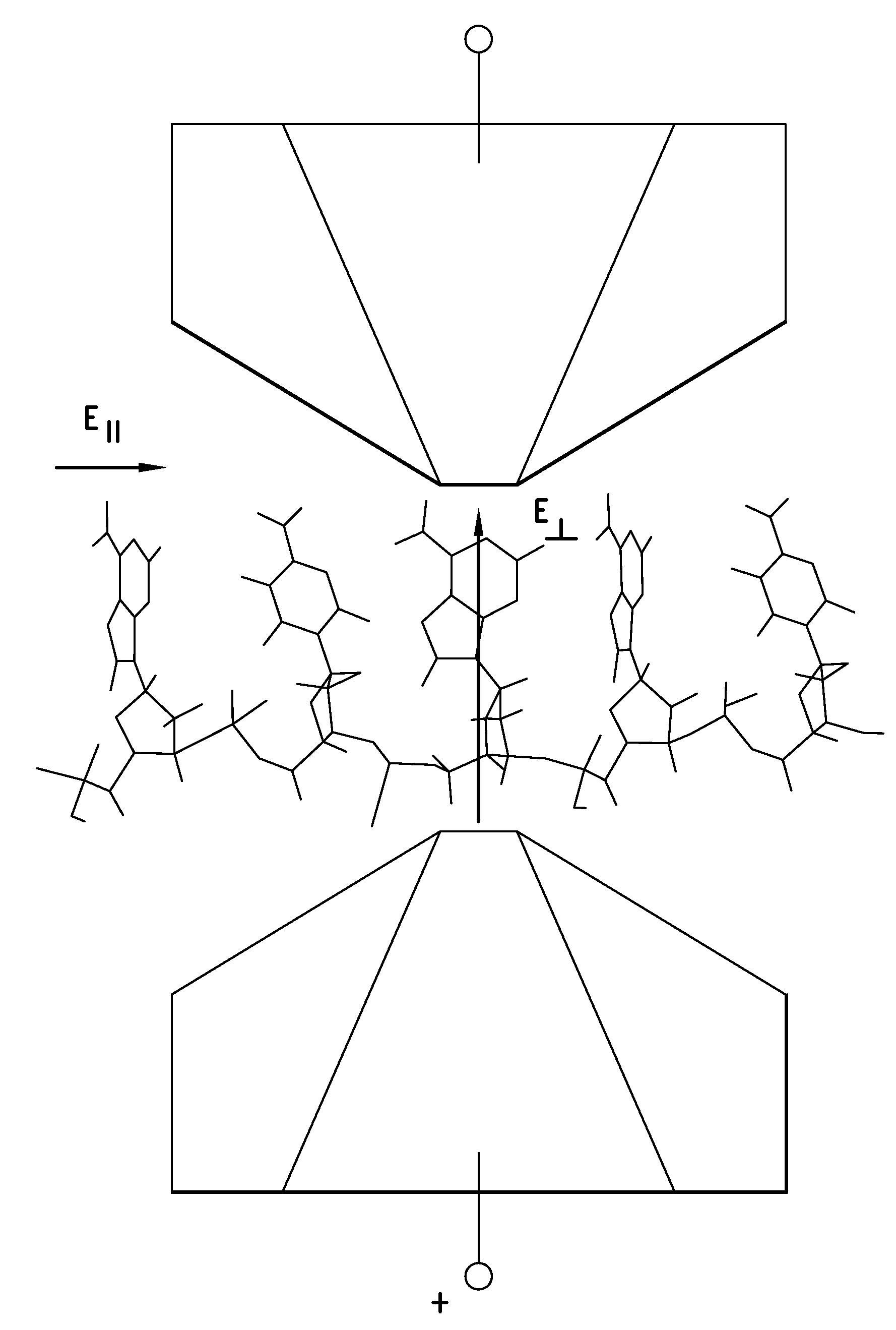
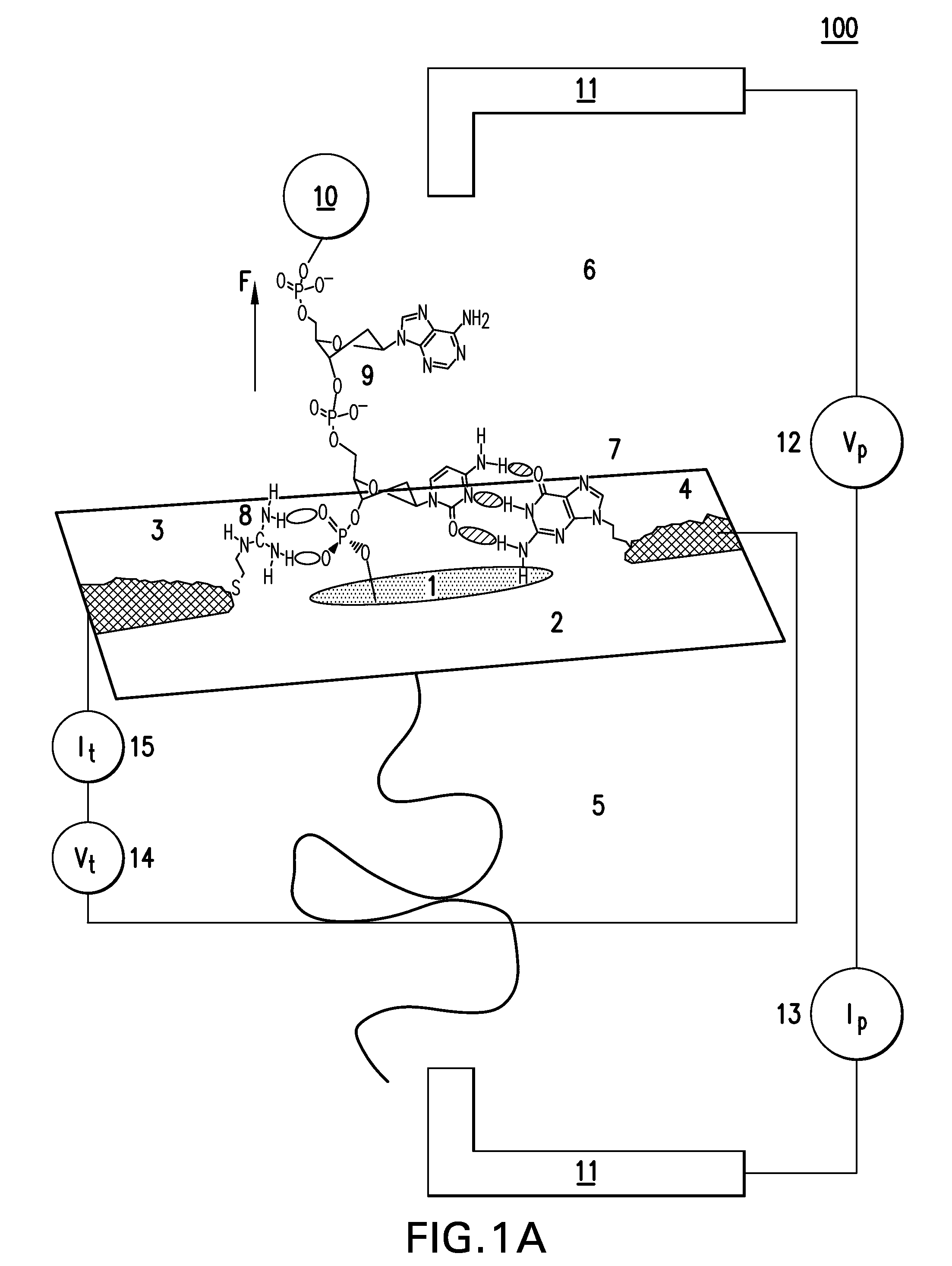
[0019]The system employs at least one device having at least two sensing electrodes spaced apart by a gap and positions on either side of a constriction, such as a nanopore. The nanopore electrode gap construction may be achieved by electrochemical assembly to produce gaps that are reformable in-situ. Alignment of a nanogap sensing electrode pair with a constriction is achieved by means of novel ‘though-pore’ plating process. Thereafter, active gap control may be used to dynamically-control the gap. Since the natural DNA bases frequently form mismatched basepairs, custom recognition elements (referred to herein as “affinity elements”) are used for molecular recognition. Each constriction is functionalized with at least one such custom affinity element. Electrophoresis, magnetic bead technology and the signal from the pore itself can be used to effect translocation through the constriction and characterization of the molecule. The system is thus configured to acquire data related to the locations of specific bases in a single strand of DNA.

Problems solved by technology

This complexity is difficult to retrieve through the assembly of contigs much shorter than the size ranges referred to in the table.
However, the chemistry required to do this is far from trivial and the use of non-natural nucleotides limits the length of the extensions.
DNA has been imaged at high resolution in water8-10 but sequencing was not possible.
In part, this is because the magnitude of the tunneling current through DNA in terms of base composition has not been easy to interpret.
In addition, the STM images themselves are not amenable to ready interpretation.
These images often reflect where the structure makes contact with the underlying metal and not the real high points of the molecule.11 This complication may also affect the recent STM imaging work of Oshiro and Umezawa.12 This difficulty rules out sequencing by imaging.
It can also be highly precessive (moving from one base to the next without “stuttering”) if the driving force is high enough.
Since Kasianowicz13 employed a biological nanopore, the alpha-hemolysin ion channel, as a sensor to characterize DNA, nanopore based biosensors have attracted much attention.21,27,28 However, biological nanopores have several shortcomings as they are unstable, fragile and fixed in size.
However, the ionic current signal has proved difficult to interpret.
With the exception of one datum52 these results are for conduction along the strand, but the problems inherent in making these measurements are the same no matter what the geometry is.
Registration of a pair of electrodes with a small (about 2-3 nm diameter) nanopore is not an easy task.
However, sequencing of translocating DNA through such pores has proven to be elusive.

Method used


Image

  • Devices and Methods for Target Molecule Characterization
  • Devices and Methods for Target Molecule Characterization
  • Devices and Methods for Target Molecule Characterization

Examples


example 1

Electrode-Tethered Guanidinium Ions can be Used to Complete an Electrical Circuit for “Reading” Bases in Single Stranded DNA

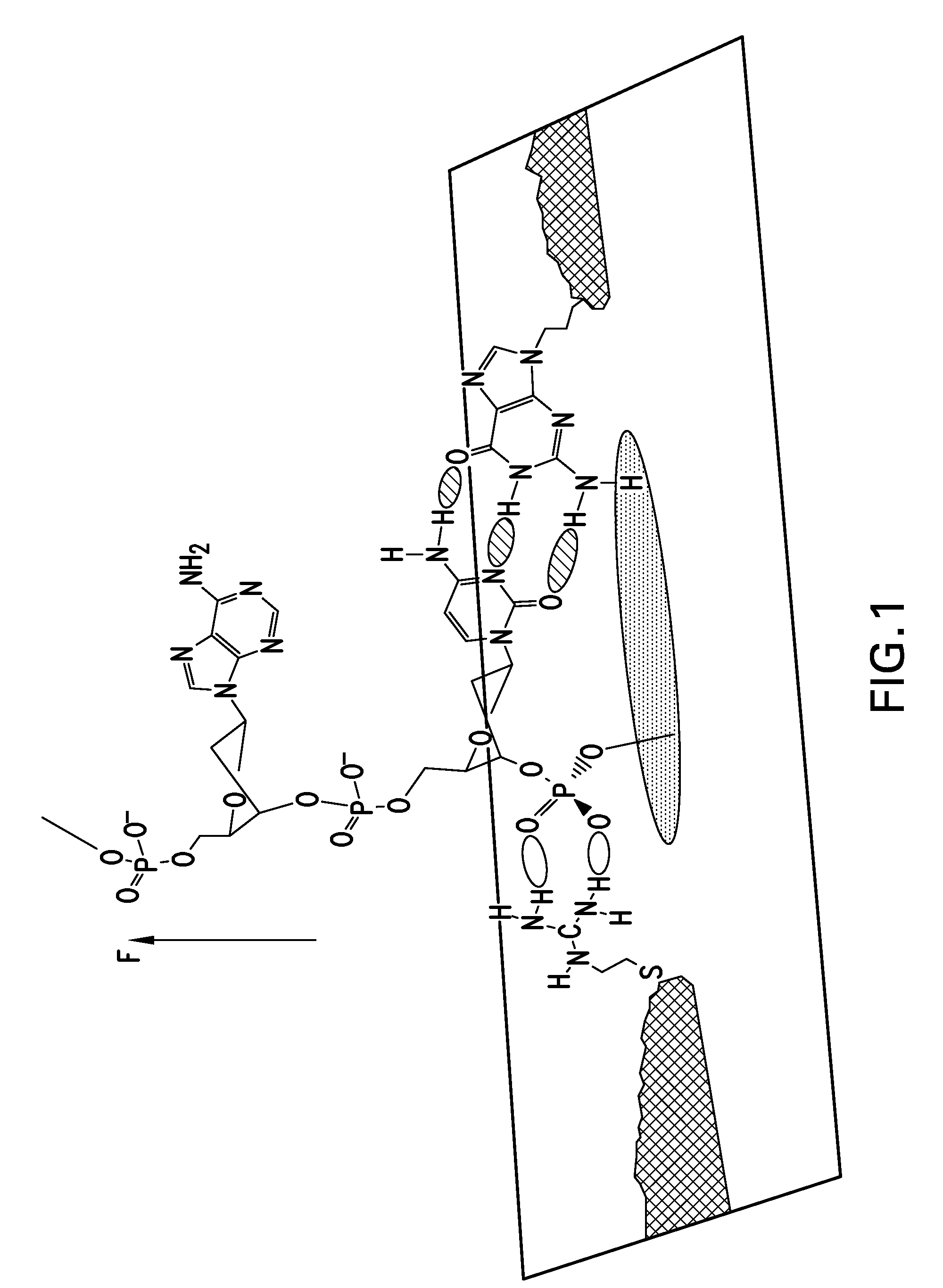
[0208]Hydrogen bonds are the molecular “Velcro” on which much of the reversible and chemically-specific bonding in biology is based.186 It has recently been shown that hydrogen bonds can also enhance electron transport significantly,12,90 observations that suggest a basis for a new type of electrical biosensor. This sensor would use two sets of hydrogen bonds to complete an electrical circuit by simultaneously binding two independent sites on a target molecule.

[0209]Electrical contacts to DNA are currently made by means of covalent modifications187 but it is possible to form “generic” hydrogen bonds to DNA by means of an interaction between the backbone phosphates and guanidinium ions.188 This then allows the construction of a “molecular sandwich” consisting of hydrogen bonded contacts to DNA via the phosphates on one side and a base on the other side as illust...

example 2

[0216]A readable signal is obtainable if the circuit is completed using a complementary DNA as second connector. Transport measurements were carried out on the DNA adlayers using gold STM probes insulated with polyethylene, functionalizing the exposed gold apex with a thiolated nucleobase.90 Either 8-mercaptoguanine (G) or 8-mercatpto-2 aminoadenine (2AA) was used. 2AA was chosen because it can form three hydrogen bonds with thymine.181

[0217]Examples of conductance vs. retraction-distance (1-Z) curves taken with these functionalized probes are given in FIGS. 34A-F, with the vertical line in each figure denoted the 1 nm distance mark. The green lower curves 340g in FIGS. 34C-34F are control data taken using bare gold probes. All of the experimental data taken in a successful run have been overlaid with no pre-selection of the curves. When no DNA is present, G and 2AA probes yield decay curves 340b over guanidinium (all curves in FIGS. 34A and B) similar to those obtained with bare p...


PUM

PropertyMeasurementUnit
forceaaaaaaaaaa
voltageaaaaaaaaaa
driving free-energyaaaaaaaaaa

Abstract

The present invention provides a device having at least one constriction that is sized to permit translocation of only a single copy of the molecule. The device has a pair of spaced apart sensing electrodes that border the constriction, which may be a nanopore. The first electrode is connected to a first affinity element and the second electrode is connected to a second affinity element. The first and second affinity elements are configured to temporarily form hydrogen bonds with first and second portions of the target molecule as the latter passes through the constriction.

Description

CROSS-REFERENCE TO RELATED APPLICATIONS[0001]The present application claims priority to U.S. Provisional Application Nos. 60 / 922,288 filed Apr. 6, 2007, 60 / 989,089 filed Nov. 19, 2007 and 61 / 022,155 filed Jan. 18, 2008. The contents of each of these provisional applications is incorporated by reference in their entirety.STATEMENT REGARDING FEDERALLY SPONSORED RESEARCH & DEVELOPMENT[0002]This invention was made with government support under NHGRI Grant Nos. 1R21HG3061, 1R21HG004378-01 and GM 21966, awarded by the National Institute of Health. The U.S. Government has certain rights in the invention.FIELD OF THE INVENTION[0003]The present invention is directed to systems, devices and methods for identifying biopolymers, such as strands of DNA, as they pass through a constriction, such as a nanopore. More particularly, the invention is directed to such systems, devices and methods in which the constriction is provided with a functionalized unit which, together with a newly translocated ...

Claims


Application Information

Patent Timeline
Patent Type & Authority Applications(United States)
IPC IPC(8): C25D5/22C12M1/34C25D9/02
CPCC12Q1/6869G01N33/48721C12Q2565/631G01N27/028G01N27/3276G01N27/3278
Inventor LINDSAY, STUART
Owner ARIZONA STATE UNIVERSITY
Learn More