Floating electrical generator for aqueducts and slow moving waterways

a technology of floating electrical generators and waterways, applied in the direction of electric generator control, machines/engines, mechanical equipment, etc., can solve the problems of limiting the generation of electricity to the daylight hours, all fundamental limitations of electric energy,

Inactive Publication Date: 2010-04-08
MARILENA BURCIK
View PDF7 Cites 23 Cited by
  • Summary
  • Abstract
  • Description
  • Claims
  • Application Information

AI Technical Summary

Benefits of technology

[0014]The power generator has a large paddle wheel having a width dimensioned to fit within an aqueduct / canal / slow-moving waterway, and having a plurality of radially projecting paddles, typically 5 or 6 or more, which are free to rotate even is slow current flow. For example, in an aqueduct section 100 feet wide at the normal water level of the aqueduct, the paddle wheel may easily be 80 feet wide and may project several feet or meters into the water, thus providing an immense area against which slow moving water may push.
[0041]allowing the slow moving agricultural or residential water to rotate the rotatable floating body.

Problems solved by technology

Power generation is rapidly becoming a central issue in the US and worldwide as inexpensive sources of energy become scarcer and increasing concerns about global environmental impact further constrain choices.
There are a fairly small number of energy generation technologies which can provide significant amounts of energy, especially electrical energy, and all have fundamental limitations.
Solar energy for electrical generation requires sunlight, limiting generation to the daylight hours.
Hydrocarbons for electricity generation suffer from price fluctuations and slowly dwindling availability, for example, as of July of 2008, crude oil costs $147 per barrel.
Nuclear energy leads to waste disposal issues which are solvable but nuclear energy is so unpopular that it limits the acceptance of nuclear energy.
Coal is fundamentally dirty to mine and burn: great numbers of coal miners suffer from “Black Lung” disease from being around coal dust.
As a result, alternative energy sources such as tidal energy, wave energy and the like are now being explored, however, hydroelectric power in landlocked areas still has large unused potential.
The slow rate of water motion of aqueducts and other slow water ways is regarded as a smaller disadvantage, but the tendency of aqueducts and the like follow contours of the ground in order to maintain a smooth gradient (typically one inch in about four feet) is a more important disadvantage: no “head” is developed.
Since aqueducts and canals are specifically laid out with smooth contours and low gradients, energy generation from aqueducts carrying residential or agricultural water is contrary to common sense.
The largest and most expensive single aqueduct system built in the US is the Central Arizona Project.

Method used


Image

  • Floating electrical generator for aqueducts and slow moving waterways
  • Floating electrical generator for aqueducts and slow moving waterways
  • Floating electrical generator for aqueducts and slow moving waterways

Examples


Embodiment Construction

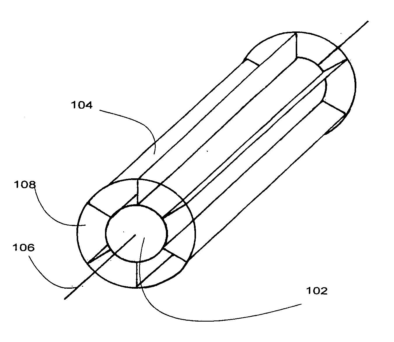
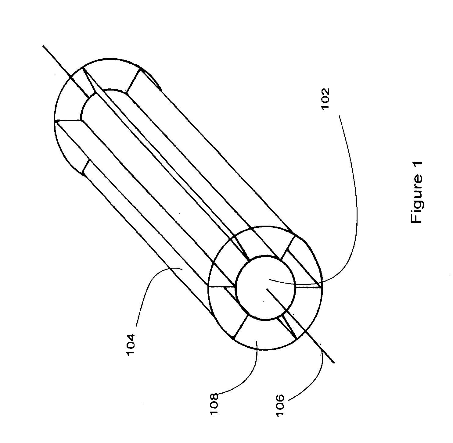
[0086]FIG. 1 is an orthogonal partially transparent view of a paddle wheel of the first embodiment of the invention. A central body may in embodiments be reduced to a central axis of rotation, however, in the presently preferred embodiment and best mode now contemplated, a physical body 102 is generally cylindrical. Other shapes may be used, either regular or irregular. In embodiments, the body may be buoyant and pontoons and other external floats may be eliminated.

[0087]The body may be made of a strong material, one which ages well during repeated cycles of exposure to air and water. Metal, suitable polymers, wood, composites and combinations thereof may be used. As noted, the body may have a central core (depicted as the entire body 102) which provides self flotation. Otherwise, reduced body mass allows less inertia, however, increased body mass may act as a flywheel and help to smooth out momentary irregularities in water flow.

[0088]Body 102 may have a length suitable for use in ...


PUM


Abstract

A power generator has a large paddle wheel having a width dimensioned to fit within an aqueduct / canal / slow-moving waterway. The paddle wheel has a plurality of radially projecting paddles which rotate even is slow current flow. Floats allow the paddle wheel to float on the surface of the water. A flexible or jointed drive shaft mechanism allows rotation of the paddle wheel to be transmitted to an electricity generator in an installation on land even if the axis of the paddle wheel and the axis of the electricity generator are not the same. The linkage (the drive shaft mechanism) in particular allows the transmission of rotary mechanical power even if the water level in the aqueduct raises the paddle wheel axis higher or lower than the axis of the electrical generator.

Description

CROSS-REFERENCE TO RELATED APPLICATIONS[0001]The application claims the priority and benefit of copending U.S. Provisional Patent Application No. 60 / 997,454 filed Oct. 2, 2007 in the name of the same inventor, Frank Burcik and also entitled METHOD AND ELECTRICAL GENERATOR FOR AQUEDUCTS AND SLOW MOVING WATERWAYS, the entire disclosure of which in incorporated herein by this reference.STATEMENT REGARDING FEDERALLY FUNDED RESEARCH[0002]This invention was not made under contract with an agency of the US Government, nor by any agency of the US Government.BACKGROUND OF THE INVENTION[0003]Power generation is rapidly becoming a central issue in the US and worldwide as inexpensive sources of energy become scarcer and increasing concerns about global environmental impact further constrain choices. There are a fairly small number of energy generation technologies which can provide significant amounts of energy, especially electrical energy, and all have fundamental limitations. Solar energy fo...

Claims


Application Information

Patent Timeline
Patent Type & Authority Applications(United States)
IPC IPC(8): F03B13/00
CPCY02E10/28F03B17/06Y02E10/30Y02E10/20
Inventor BURCIK, FRANK
Owner MARILENA BURCIK
Why Eureka
Try Eureka