Power system

a power system and power supply technology, applied in the field of power systems, can solve the problems of limiting the power consumption of the device during standby, affecting the power supply of the device, and reducing the power consumption at a minimum, so as to reduce the power drawn and reduce the power consumption

Active Publication Date: 2010-04-08
PHILIPS IP VENTURES BV
View PDF3 Cites 396 Cited by
  • Summary
  • Abstract
  • Description
  • Claims
  • Application Information

AI Technical Summary

Benefits of technology

[0012]One embodiment for reducing power consumption includes providing a primary unit capable of selectively operating in a detection mode, an identification mode, and a power supply mode. The method also includes detecting presence of an object within proximity of the primary unit during the detection mode, identifying the object during identification mode, and supplying power wirelessly to the secondary device during the power supply mode. The detection mode includes restricting the supply of power to at least a portion of the primary unit, detecting the presence of an object within proximity of the primary unit, and either staying in the detection mode or entering the identification mode in dependence upon the detecting. The identification mode includes identifying whether the detected object is a valid secondary device, upon identifying a valid secondary device entering the power supply mode, and upon failing to identify a valid secondary device entering the detection mode. The power supply mode includes supplying power to the primary unit at a higher level than during the detection mode, the higher level of power sufficient for the primary unit to function as a wireless power supply.
[0013]According to a first aspect of the invention there is provided a method for reducing the power drawn by a primary unit capable of interacting with a secondary device, separable from the primary unit, the method having the following modes:

Problems solved by technology

However, when there is no device on the unit (or when the only devices on the unit are fully charged) it is possible to keep the power consumption at a minimum.
The power level of the pulses in standby mode are sufficiently high to transfer enough power to the portable device so that it can communicate back, because it is possible that the device's batteries may be fully depleted.
There is therefore a limit to how low the power consumption can be during standby.
In addition to the power for determining the presence of devices to be powered, there are practical limitations that increase the power consumption.
This means that mains rectification losses are always present and can be considerable.
In some scenarios, multiple DC voltages are used and it would not be practical to start these up within the pulse duration, so DC conversion losses might always be present.
The microprocessor in the unit that drives the pulse width modulation for the inverter typically is relatively high performance and consumes a certain amount of power continuously.
These and other factors make it challenging for a wireless power system to have low standby power.
However, this considerably detracts from the main benefit the system provides—the convenience of just putting the device on the wireless power supply.
This means that seven times as much energy is wasted in standby compared to the energy used.
However, these are not applicable to wireless power systems.
In addition to wireless power systems, other systems for example contactless card systems also suffer from power wastage in standby.

Method used


Image

  • Power system
  • Power system
  • Power system

Examples


Embodiment Construction

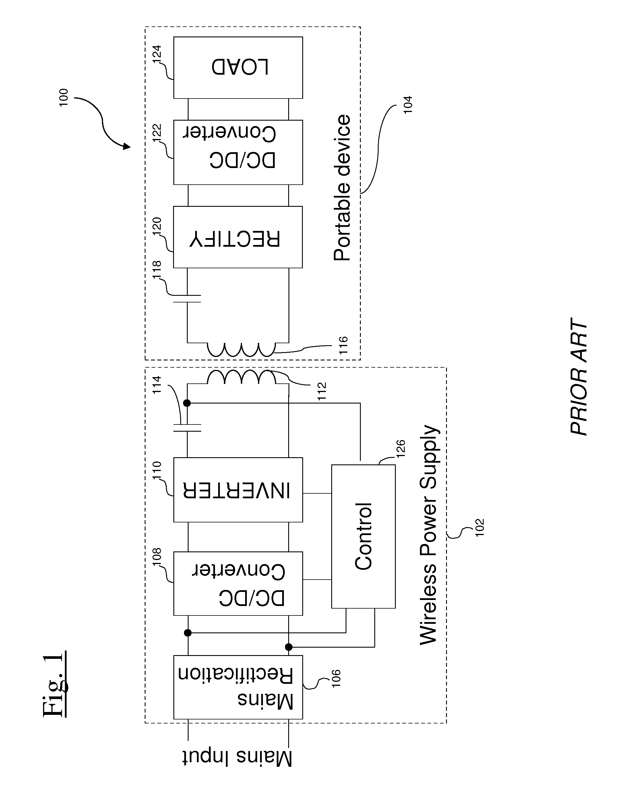
[0189]FIG. 1 shows an example of a wireless power system 100, which uses electromagnetic induction. There is a wireless power supply 102 which takes electrical power and transmits this power to a portable device 104. The charger takes an AC electrical input from the mains. This is rectified using a mains rectifier 106 to produce DC power. This DC power is down-converted to a lower voltage using a DC-DC Converter 108. The down-converted voltage is used to drive an Inverter 110. The Inverter 110 generates an AC voltage which is applied to the tank circuit, which includes a capacitor 114 and a primary coil 112. The portable device 104 has a secondary coil 116, and sometimes a resonant capacitor 116, which couples to the primary coil 112, thereby producing a voltage. This voltage is rectified with rectifier 120 and is down-converted to a lower voltage using a DC / DC converter 122 to supply the Load 124. The Load 124 is representative of the power requiring parts of the portable device 10...


PUM


Abstract

The present invention provides methods and apparatus for reducing power consumption. One method includes detecting the presence of an object, identifying whether the object is a valid device and restricting power if its not a valid device. Another method includes temporarily applying a low amount of power to the primary unit to detect a load, supplying more power to determine if its a valid secondary device, and restricting power if its not. An apparatus for reducing power consumption includes two power inputs, where the lower power input powers a sense circuit. A switch selectively decouples the higher power input from the primary subcircuit during detection mode and couples the higher power input to the primary subcircuit during power supply mode.

Description

BACKGROUND OF THE INVENTION[0001]It is more convenient to be able to power portable devices without the need to plug in a traditional power cable into the device. For example some wireless power systems include a portable device that when placed near a wireless power supply unit can receive power without the need for a direct electrical contact. However, when there is no device on the unit (or when the only devices on the unit are fully charged) it is possible to keep the power consumption at a minimum.[0002]Some wireless power units have a standby mode, whereby it periodically transmits power for a short period to look for devices. If the unit detects a valid device that is requesting power and determines that there are no foreign objects that would get hot or hinder power transfer in the vicinity then the unit may come out of standby. The power level of the pulses in standby mode are sufficiently high to transfer enough power to the portable device so that it can communicate back,...

Claims


Application Information

Patent Timeline
Patent Type & Authority Applications(United States)
IPC IPC(8): H02J4/00
CPCH02J5/005H02J7/025H02M3/28H04B5/0037G01V3/10H02J7/00045H02J50/402H02J50/80H02J50/12H02J50/60G06F1/263H02J50/90H02J50/40
Inventor FELLS, JULIAN ANDREW JOHNBAARMAN, DAVID W.
Owner PHILIPS IP VENTURES BV
Why Eureka
Try Eureka