

Organic electroluminescent element, display device and lighting device
a technology of electroluminescent elements and display devices, applied in the direction of discharge tubes/lamp details, organic chemistry, discharge tubes luminescnet screens, etc., can solve the problems of poor emission lifetime of elements compared to conventional elements, inability to achieve a level of practical use, and insufficient emission efficiency and emission lifetime. achieve the effect of long emission lifetime and high emission efficiency
- Summary
- Abstract
- Description
- Claims
- Application Information
AI Technical Summary
Benefits of technology
Problems solved by technology
Method used
Image

Examples
example 1
Preparation of Organic EL Element 1-1
[0195]Patterning was applied to a substrate (NA45 produced by NH Techno Glass Corp.) on which a 100 nm film of ITO (indium tin oxide) was formed, as a anode, on the above 100 mm×100 mm×1.1 mm glass substrate. Thereafter, the above transparent support substrate provided with the ITO transparent electrode underwent ultrasonic washing with isopropyl alcohol, dried via desiccated nitrogen gas, and underwent UV ozone washing for 5 minutes.
[0196]The resulting transparent support substrate was fixed via the substrate holder of a commercial vacuum deposition apparatus. Separately, 200 mg of α-NPD was placed in a molybdenum resistance heating boat, 200 mg of CBP as a host compound was placed in another molybdenum resistance heating boat, 200 mg of BCP was placed in further another molybdenum resistance heating boat, 100 mg of Exemplified Compound 1-1 was placed in yet another molybdenum resistance heating boat, and 200 mg of Alq3 was placed in still yet a...
example 2
Preparation of Organic EL Element 2-1
[0211]Patterning was applied to a substrate (NA45 produced by NH Techno Glass Corp.) on which a 100 nm film of ITO (indium tin oxide) was formed, as a anode, on the above 100 mm×100 mm×1.1 mm glass substrate. Thereafter, the above transparent support substrate provided with the ITO transparent electrode underwent ultrasonic washing with isopropyl alcohol, dried via desiccated nitrogen gas, and underwent UV ozone washing for 5 minutes.
[0212]The resulting transparent support substrate was fixed via the substrate holder of a commercial vacuum deposition apparatus. Separately, 200 mg of α-NPD was placed in a molybdenum resistance heating boat, 200 mg of CBP as a host compound was placed in another molybdenum resistance heating boat, 100 mg of Ir-1 was placed in further another molybdenum resistance heating boat, and 200 mg of Alq3 was placed in still further another molybdenum resistance heating boat, and the resulting boats were fitted in the vacuum...
example 3
Preparation of Full Color Display Device
(Preparation of Blue Light Emitting Element)
[0223]Organic EL element 1-9 of Example 1 was employed as a blue light emitting element.
(Preparation of Green Light Emitting Element)
[0224]Organic EL element 2-4 of Example 2 was employed as a green light emitting element.
(Preparation of Red Light Emitting Element)
[0225]A red light emitting element was prepared in the same manner as Organic EL Element 1-1 in Example 1, except that the host compound was replaced with CBP, and the dopant was replaced with Ir-14. The resulting element was employed as a red light emitting element.
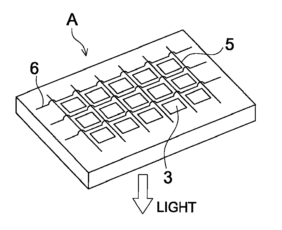
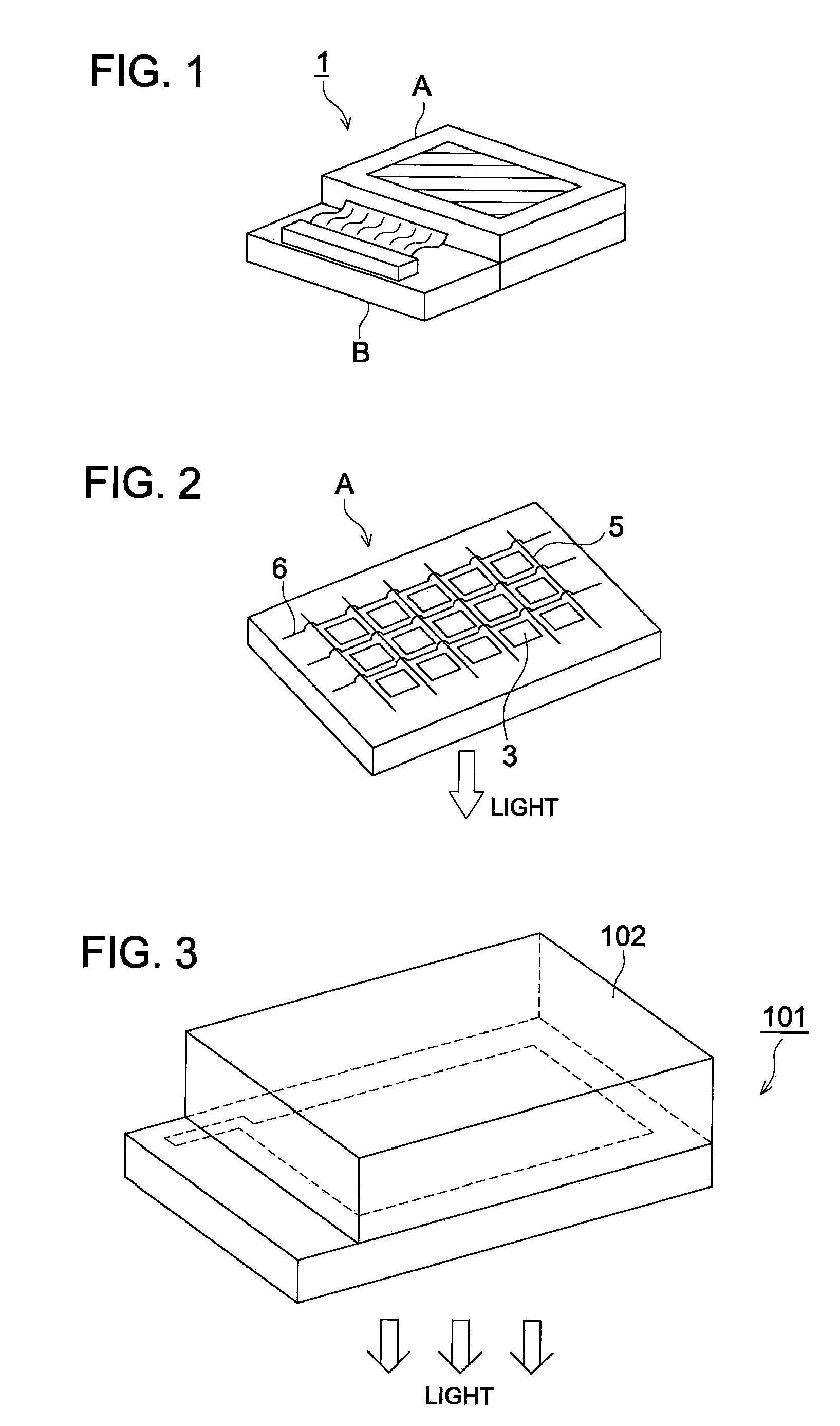
[0226]The red, green, and blue light emitting organic EL elements, prepared as above, were arranged parallel on one substrate, and an active matrix system full-color display device which had the configuration, shown in FIG. 1, was prepared. In FIG. 2, shown is a schematic view of display section A of the above prepared display device.
[0227]Namely, on one substrate, arranged is a...
PUM
| Property | Measurement | Unit |
|---|---|---|
| Electroluminescence | aaaaa | aaaaa |
| Luminous efficiency | aaaaa | aaaaa |
| Phosphorescence quantum yield | aaaaa | aaaaa |
Abstract
Description
Claims
Application Information