
Gear pump

a gear pump and gear holder technology, applied in the direction of liquid fuel engines, machines/engines, rotary piston liquid engines, etc., can solve the problems of excessive oil supply into the engine, engined power loss, etc., to improve the operation reliability of the gear pump, improve the operation efficiency of the gear holder, and improve the effect of pump capacity variability

Active Publication Date: 2010-04-08
TBK
View PDF9 Cites 8 Cited by
  • Summary
  • Abstract
  • Description
  • Claims
  • Application Information

AI Technical Summary

Benefits of technology

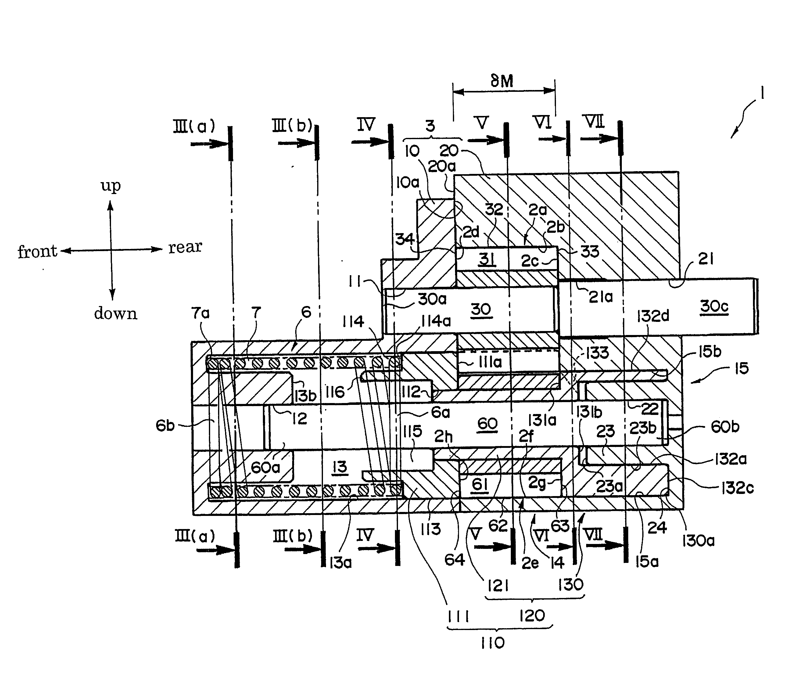
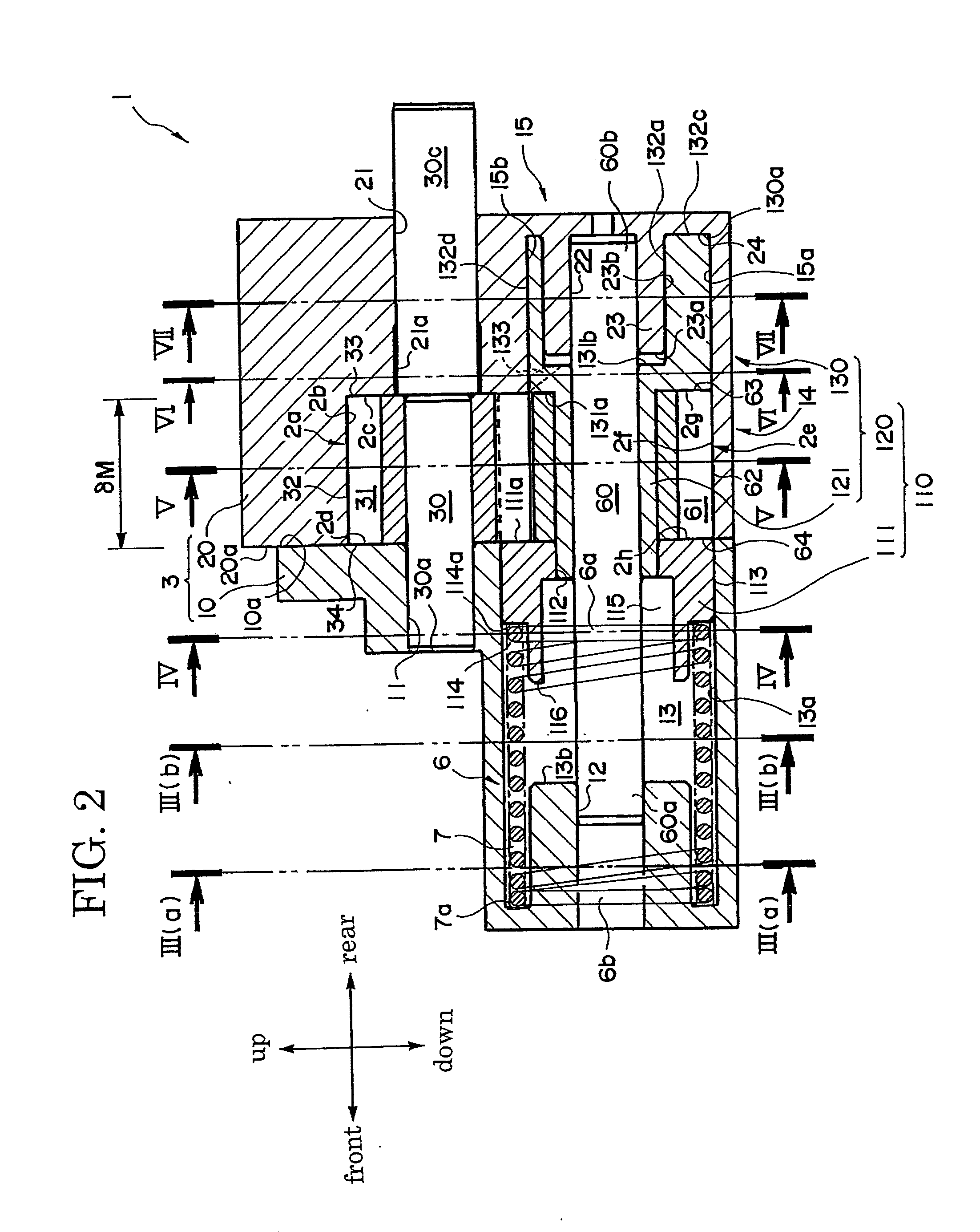
[0009]In the gear pump according to the invention, the gear holder holds the second gear rotatable, and the gear holder holding the second gear is supported axially movable on the second support shaft. In this arrangement, on the part of the gear holder where the second gear is supported, a sliding friction occurs in the circumferential direction (i.e., in the direction perpendicular to the shaft) when the second gear rotates. On the other hand, on the surface of the second support shaft, a sliding friction occurs in the axial direction when the gear holder moves in the axial direction. Because each sliding friction occurs on a different part, these frictional resistances do not interfere with each other. As a result, the rotation of the second gear and the axial movement of the gear holder are secure and reliable, improving the operation reliability of the gear pump and the efficient variability of the pump capacity.
[0010]In addition, the pressing force acts directly on the gear holder because the piston, which is to be subjected to the pressing force, is provided on the other side face of the one side wall or the other side face of the other side wall. This arrangement prevents any loss in conveying the pressing force, so the pressing force, which is used for the gear holder to move axially, itself can be reduced for increasing the operational efficiency of the gear holder.
[0011]Furthermore, the internal flow passage is provided inside the gear holder for connecting, in fluid communication, the discharge port to the enclosed space, which is provided on the back side of the piston around the outer periphery of the second support shaft, and the pressing force is made to act on the piston by leading the fluid into this enclosed space. This arrangement makes the pressing force available without increasing the number of necessary components, and thus presents a possibility that the gear pump be manufacturing with a reduced cost.

Problems solved by technology

On the other hand, as the output of the engine becomes larger, and thereby the rotational speed of the pump grows higher, the oil being supplied into the engine becomes excessive.
In this condition, there is a possibility that a large driving force is consumed by the oil pump, which may lead to a power loss of the engined.

Method used


Image

  • Gear pump
  • Gear pump
  • Gear pump

Examples


Embodiment Construction

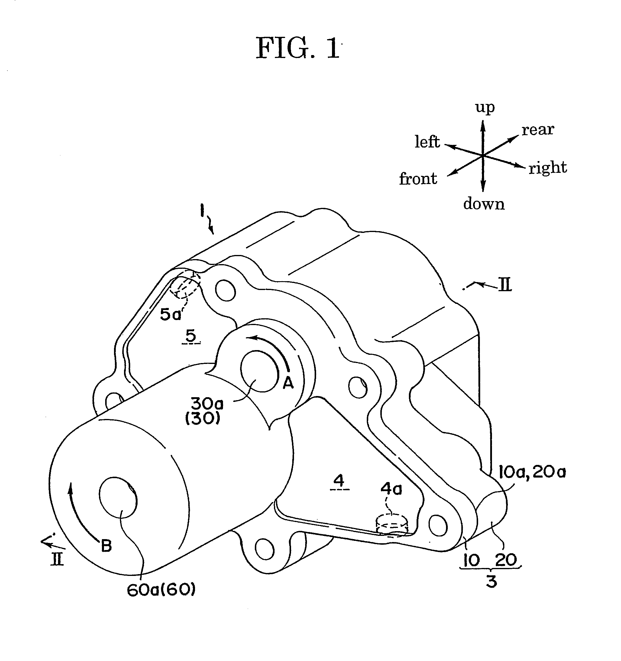
[0021]Now, an embodiment of the invention is described with reference to these drawings. An oil pump 1 is shown in FIG. 1 through FIG. 8 as an example of gear pump according to the invention. For the sake of descriptive convenience, the directions of the oil pump are defined as indicated by arrows “front”, “rear”, “up” and “down” in FIG. 2, and the directions that are perpendicular to the paper that carries the drawing are defined as “right” and “left” directions. This oil pump 1, which is mounted in a vehicle (not shown) and uses an engine as driving source, takes in lubricating oil pooled in an oil tank (for example, an engine oil pan), which is provided in the vehicle, and discharges it into lubricating oil passages each connected to an appropriate part of the engine.

[0022]The oil pump 1 is an external contact type gear pump and mainly comprises a casing 3, a return spring 6, a drive gear 31, a driven gear 61, a drive shaft 30, a transmission shaft 30c, a driven shaft 60 and a ge...


PUM


Abstract

An oil pump includes a drive gear, which rotates with a drive shaft, a driven gear, which meshes with the drive gear and is supported rotatable on a driven shaft, and a casing having a pump chamber, which accommodates the drive gear and the driven gear. The casing of the gear pump is provided with an intake port and a discharge port, which are in fluid communication with the pump chamber, so that oil is sucked through the intake port and discharged through the discharge port. A gear holder is provided in the casing such that the gear holder supports the driven gear rotatable and holds both sides of the driven gear while the gear holder itself is being supported axially movable by the driven shaft. The gear holder holding the driven gear moves axially by receiving a biasing force and also a pressing force acting against the biasing force.

Description

TECHNICAL FIELD[0001]The present invention relates generally to a gear pump that comprises two intermeshing gears for transporting a fluid and particularly to a gear pump the meshing width of whose two gears is variable.TECHNICAL BACKGROUND[0002]Generally, the capacity of a gear pump is determined by, for example, the tooth depth and tooth width of the gears, and the discharge flow rate is determined by the capacity and the rotational speed of the gears (i.e., the rotational speed of the pump). In a case where this gear pump is used as an oil pump for supplying lubricating oil into, for example, a vehicular engine, the capacity of the oil pump is set to supply oil at a sufficient amount for the lubrication even if the output of the engine as driving source is small, and therefore, the rotational speed of the pump is relatively low. On the other hand, as the output of the engine becomes larger, and thereby the rotational speed of the pump grows higher, the oil being supplied into the...

Claims


Application Information

Patent Timeline
Patent Type & Authority Applications(United States)
IPC IPC(8): F04C14/20
CPCF04C14/185F04C2/18
Inventor SHINOZAKI, KEISUKE
Owner TBK
Learn More