
Composite optical film

Inactive Publication Date: 2010-04-08
ETERNAL MATERIALS CO LTD
View PDF16 Cites 23 Cited by
  • Summary
  • Abstract
  • Description
  • Claims
  • Application Information

AI Technical Summary

Benefits of technology

[0009]By extensive studies, the inventors of the present invention found a composite optical film that possesses both light-diffusion and light-converging properties so as to effectively enhance the efficiency of light, and is thinner so as to make the assembly of backlight modules easier.
[0010]The primary object of the present invention is to provide a composite optical film effective in eliminating rainbow effect, which comprises a substrate having diffusion micro-structures and a structured surface on one side of the substrate wherein said composite optical film has an internal diffusion haze of no less than 5% as measured according to JIS K7136 standard method.

Problems solved by technology

Since the light converging film comprises regularly arranged columnar structures with constant widths, the light rays from the light converging film are liable to optically interfere with the reflected or refracted light rays from other films of the display or with other light rays refracted or reflected by the light converging film itself, thereby resulting in rainbow effect, bright and dark stripes, Moiré or Newton ring in the LCD.
However, a top diffuser is expensive and an extra optical film will increases the thickness and complexity of the backlight module such that the backlight module cannot meet the current requirements for light and thin devices.

Method used


Image

  • Composite optical film
  • Composite optical film
  • Composite optical film

Examples


example 1

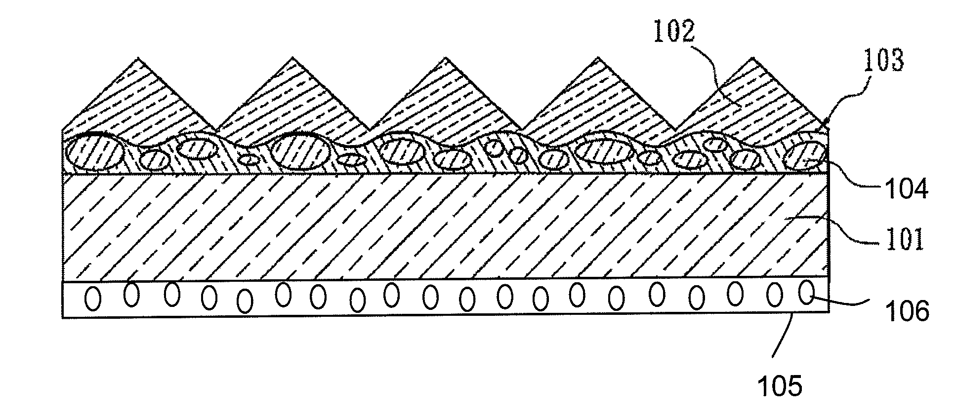
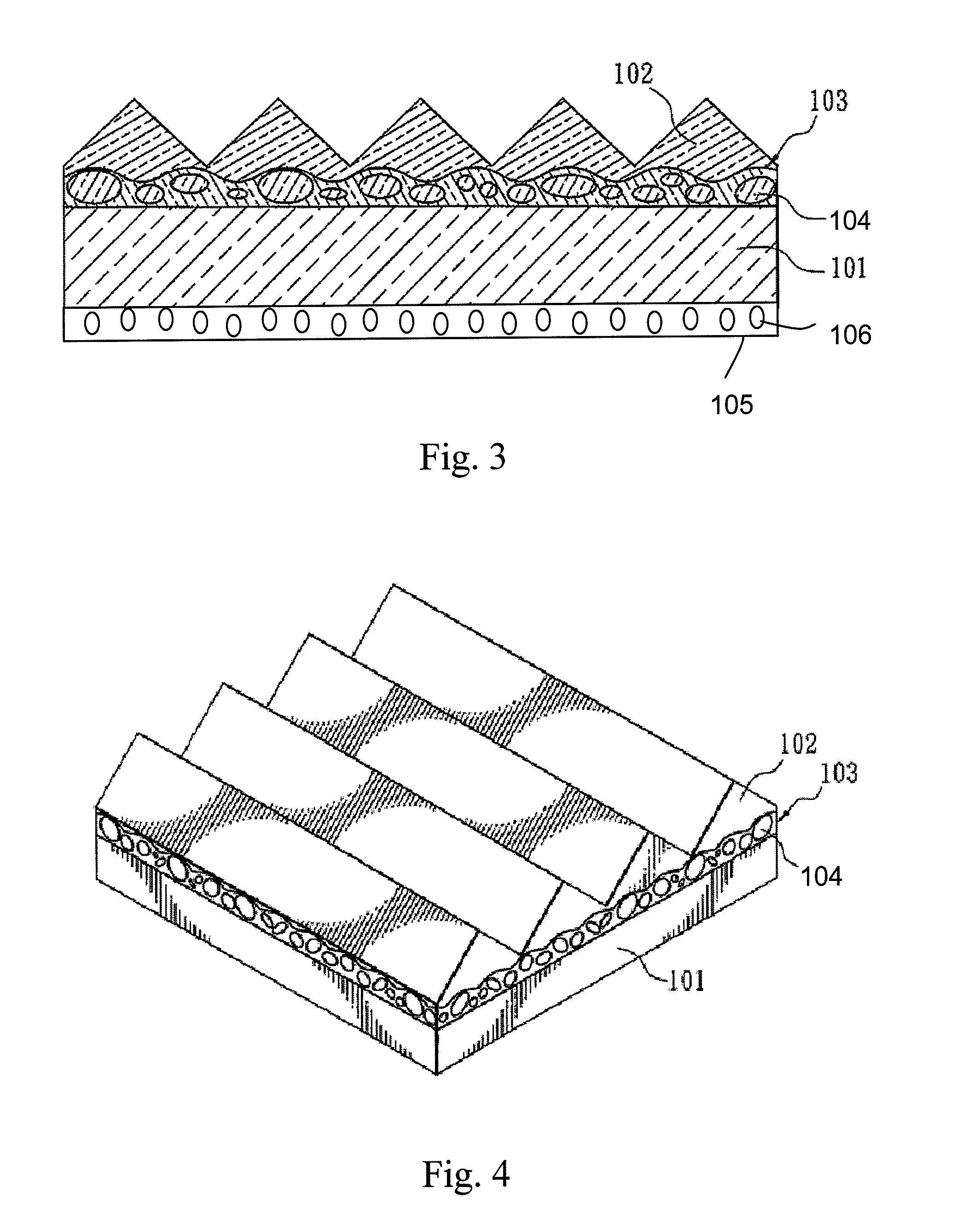
[0055]A composite optical film according to the present invention was prepared by applying an acrylate resin coating layer of a thickness of about 15 μm onto the diffusion micro-structures of the substrate that has a haze of 50% as recorded in Table 1, forming prism structures on the coating layer by roller embossing, and then curing the structures by high energy UV light.

example 2

[0056]A composite optical film according to the present invention was prepared by applying an acrylate resin coating layer of a thickness of about 15 μm onto the diffusion micro-structures of the substrate that has a haze of 90% as recorded in Table 1, forming prism structures on the coating layer by roller embossing, and then curing the structures by high energy UV light.

examples 3 to 5

[0057]In order to address the problem associated with bright and dark stripes and enhance the scratch resistance of the optical film, hard coat solutions were prepared with components E, F, G and H in the amounts provided in Table 2 for use in the preparation of scratch-resistant layers. Scratch-resistant layers with a thickness of about 5 μm were prepared by respectively applying the hard coat solutions made according to Table 2 onto the film made according to Example 1 on the side opposite to the structured surface. After drying, the composite optical films having a scratch-resistant layer according to the present invention were obtained.

[0058]The hard coat solutions made according to Table 2 were respectively applied onto transparent PET films having a thickness of 188 μm [U34®, Toray Company] to prepare scratch-resistant layers, and then, in the absence of any structures on the other side of the substrates, the haze values of the scratch-resistant layers were measured according ...


PUM


Abstract

The present invention relates to a composite optical film, which comprises a substrate having diffusion micro-structures and a structured surface on one side of the substrate wherein said composite optical film has an internal diffusion haze of no less than 5% as measured according to JIS K7136 standard method. The composite optical film of the present invention has both light-diffusion and light-converging properties. The composite optical film of the present invention, when utilized in a liquid crystal display (LCD), can not only effectively enhance the luminance of the LCD panel but also avoid light dispersion and Moiré phenomena that may occur when said composite optical film is stacked with other material films.

Description

BACKGROUND OF THE INVENTION[0001]1. Field of the Invention[0002]The present invention relates to a composite optical film, particularly, a composite optical film for use in liquid crystal displays. The composite optical film of the present invention has both light-diffusion and light-converging properties and can reduce light dispersion and Moiré phenomena that may occur when said composite optical film is stacked with other material films.[0003]2. Description of the Prior Art[0004]In general, a liquid crystal display (LCD) is mainly composed of a panel and a backlight module. The panel comprises, for example, indium tin oxide (ITO) conductive glass, liquid crystals, an alignment film, a color filter, a polarizer and a driving integrated circuit. The backlight module comprises, for example, lamps, a light guide plate, and various optical films. Since a liquid crystal panel does not emit light itself, a backlight module, as a brightness source, is an important element for the display...

Claims


Application Information

Patent Timeline
IPC IPC(8): B32B3/00
CPCG02B5/0221G02B5/0242Y10T428/24612G02B5/0278G02B5/0268G02B5/02G02B5/04G02F1/1335
Inventor WANG, HSUNG-HSINGLIU, SUE-HONGLIN, PO-WENCHEN, PEI-HSIN
Owner ETERNAL MATERIALS CO LTD
Features
  • Generate Ideas
  • Intellectual Property
  • Life Sciences
  • Materials
  • Tech Scout
  • Unparalleled Data Quality
  • Higher Quality Content
  • 60% Fewer Hallucinations
Learn More