
Method of manufacturing a bent product and an apparatus and a continuous line for manufacturing the same

a manufacturing method and technology of a continuous line, applied in the direction of shaping tools, heating/cooling devices, furnaces, etc., can solve the problems of inability to achieve desired hardening accuracy, inability to ensure desired hardening accuracy, and difficulty in complex control of cooling rate, etc., to achieve desired dimensional accuracy, high strength, and high strength

Inactive Publication Date: 2010-04-15
SUMITOMO METAL IND LTD +1
View PDF4 Cites 12 Cited by
  • Summary
  • Abstract
  • Description
  • Claims
  • Application Information

AI Technical Summary

Benefits of technology

"The patent text describes a method and apparatus for manufacturing bent products with high strength and accuracy. The method and apparatus can efficiently perform bending with a variety of bending shapes, such as S-bending and three-dimensional bending, with high precision. The apparatus includes a fixed die and a movable gyro-die, which can move in three dimensions to produce the desired bending shape. The method and apparatus can be used to manufacture automobile parts with high reliability. The technical effects of the invention include improved manufacturing efficiency, high strength, and precise control over bending shape."

Problems solved by technology

Therefore, the member being worked cannot be fed at a high speed, and each time gripping of the member being worked by the arm is repeated, it is necessary to return the arm, so the feed speed of the member being worked greatly fluctuates, it becomes difficult to control the cooling rate in a complicated manner, and a desired hardening accuracy cannot be achieved.
It becomes necessary to control the heating and cooling rate in a complicated manner, but even if doing so, non-uniform strains develop, and a desired hardening accuracy cannot be guaranteed.
Therefore, variations in the bent shape develop, and when dealing with a high-strength material, delayed fracture due to residual stresses occurs, and it is difficult to manufacture an automobile part requiring high reliability.
However, in the bending apparatus with high-frequency heating disclosed in Patent Document 3, there is no means for clamping both side surfaces of the material being worked.
Therefore, deformation caused by residual stress due to cooling after high frequency heating easily occur, which makes it difficult to guarantee a prescribed dimensional accuracy.
In addition, there are limitations on the working speed and it is difficult to increase the degree of working.
Therefore, the surfaces of both the fixed die and the movable gyro-die easily develop seizing scratches when holding the metal material.
However, supply of the cooling fluid is not for the purpose of quenching heat treatment of the metal material being bent, so it is not possible to manufacture a bent product having a high strength such as at least 900 MPa by quenching.
In addition, due to heating of the metal material, the surface of the movable gyro-die easily develops seizing scratches, so further improvements as a bending apparatus is needed.

Method used


Image

  • Method of manufacturing a bent product and an apparatus and a continuous line for manufacturing the same
  • Method of manufacturing a bent product and an apparatus and a continuous line for manufacturing the same
  • Method of manufacturing a bent product and an apparatus and a continuous line for manufacturing the same

Examples


example 1

[0225]The present invention will be explained more concretely while referring to examples.

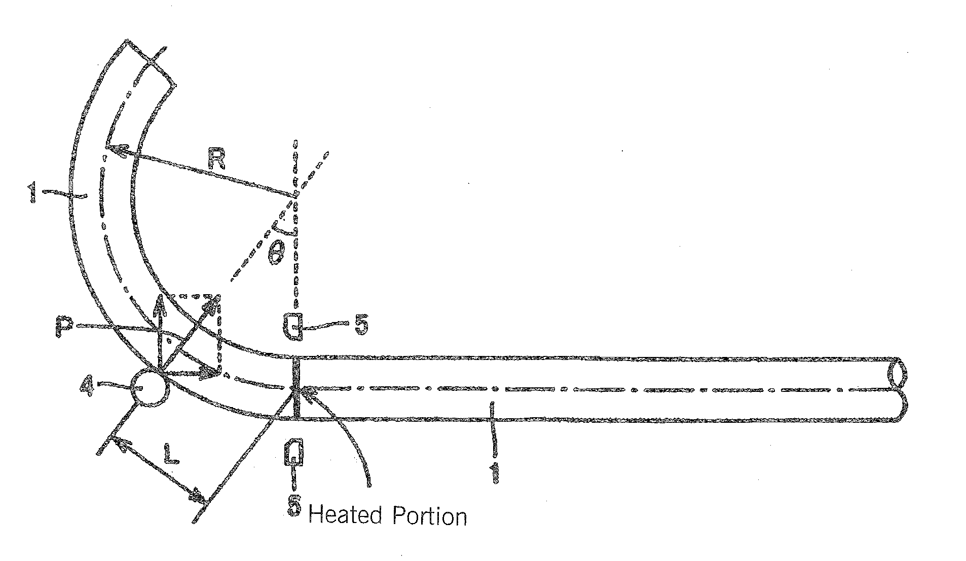
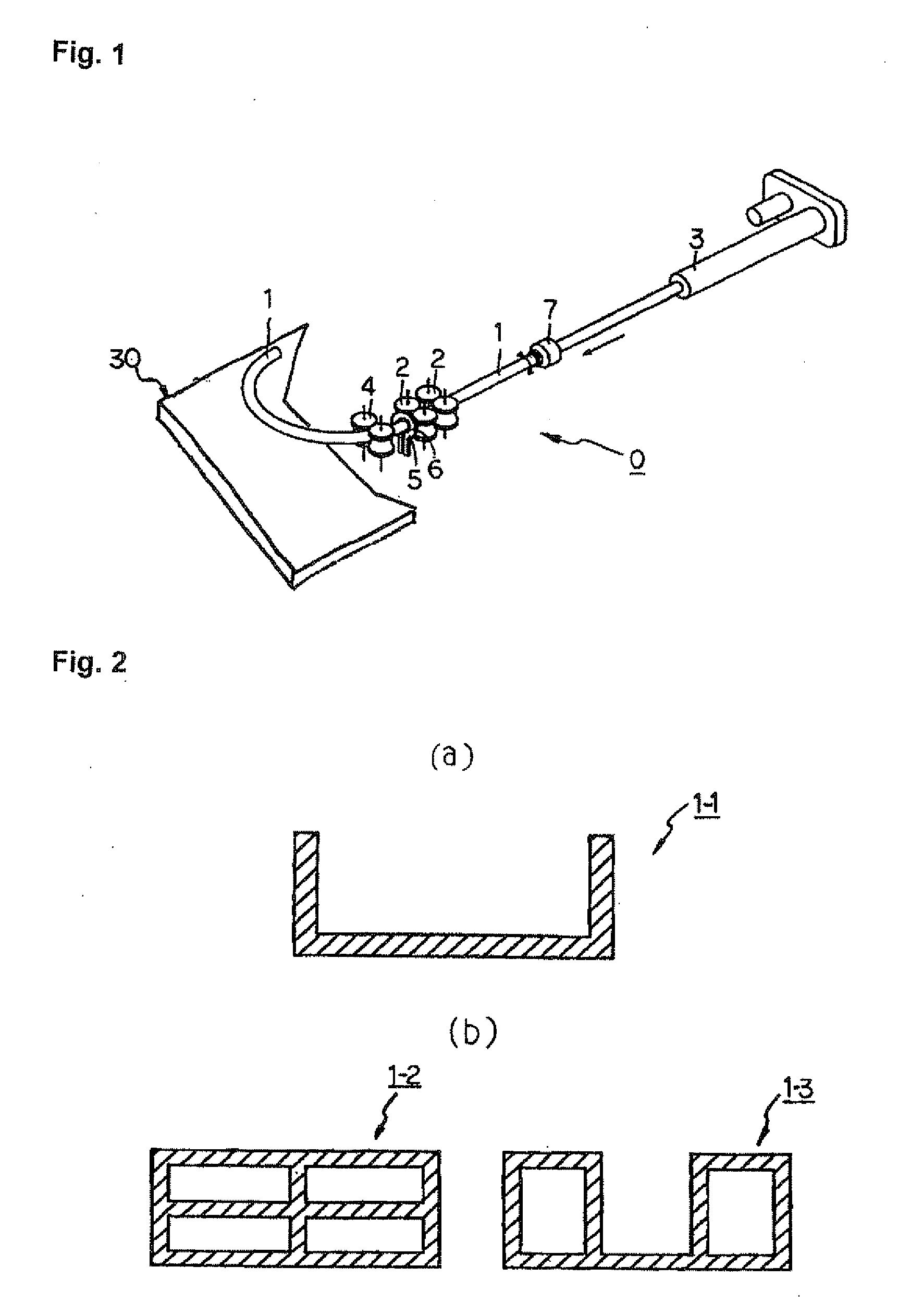
[0226]Using a steel pipe with a wall thickness of 1.6 mm and a square cross section having a height and width each measuring 40 mm as a starting material, a bent product having the external appearance shown in FIG. 24 was manufactured using the bending apparatus according to the present invention which was explained while referring to FIG. 1.

[0227]In this example, bent products prepared in a conventional example which was manufactured without using a support according to the present invention, Example 1 of the present invention which was manufactured using the support guide 30A shown in FIG. 11, and Example 2 of the present invention which was manufactured using the support guide 30B shown in FIG. 12 were measured using a non-contacting three-dimensional measuring device to determine the maximum deviation from a target value (dimensional accuracy).

[0228]The support guide 30A shown in FIG. 11 ha...

example 2

[0232]Using a steel pipe having a wall thickness of 2.1 mm and a circular transverse cross-sectional shape with an outer diameter of 31.8 mm as a starting material, a product having a completely three-dimensional spiral bend and having the external appearance shown in FIG. 28(a) and the dimensions shown in FIG. 28(b) was manufactured using a bending apparatus according to the present invention which was explained with respect to FIG. 1.

[0233]Products of Conventional Example 2, which was manufactured without using the support of the present invention, and Example 3 of the present invention, which was manufactured using the support guide 30G shown in FIG. 17, were measured using a non-contacting three-dimensional measuring device to determine the maximum value of the deviation from a target value (dimensional accuracy).

[0234]In this example, the support guide 30G shown in FIG. 17 was supported using the articulated robot 31-1 shown in FIG. 35. The support guide was used to clamp the e...

example 3

[0237]Using a steel pipe with a wall thickness of 1.8 mm and a rectangular cross-sectional shape with a height of 50 mm and a width of 70 mm as a starting material, a front side member, which is a reinforcing member of an automobile body, having the two-dimensional shape shown in FIG. 36 was manufactured using the bending apparatus according to the present invention which was explained while referring to FIG. 1.

[0238]Products of Conventional Example 3, which was manufactured without using a support guide of the present invention, and Example 4 of the present invention, which was manufactured using the support guide 30H of FIG. 37, were measured using a non-contacting three-dimensional measurement device to determine the maximum value of the deviation from a target value (dimensional accuracy).

[0239]The support guide 30H shown in FIG. 37 clamped the end of the metal material and had a mechanism which could adjust the clamping angle on a table 53. The table had precision ball screws 5...


PUM

PropertyMeasurementUnit
tensile strengthaaaaaaaaaa

Abstract

A method and apparatus for three-dimensionally bending a metal material are provided. A product intermittently having a bent portion which curves three-dimensionally and a quenched portion is manufactured by a bending method which performs bending downstream of a support means while feeding a metal material which is supported by the support means from an upstream side towards a downstream side. A portion of the metal material is heated by a heating means for the metal material downstream of the support means, a bending moment is imparted to the portion of the metal material which was heated by the heating means to carry out bending by three-dimensionally changing the position of a movable roller die which is disposed downstream of the heating means and has a plurality of rolls which feed the metal material which was heated by the heating means in the axial direction, and the metal material is quenched by spraying a cooling medium at the portion of the metal material which was heated by the heating means by a cooling means disposed between the heating means and the movable roller die. Errors in a product due to bending are suppressed by supporting a portion of the metal material which has exited from the movable roller die.

Description

TECHNICAL FIELD[0001]This invention relates to a method of manufacturing a bent product (a product formed by bending), and a manufacturing apparatus and a continuous manufacturing line therefor. More particularly, it relates to a manufacturing method, a manufacturing apparatus, and a continuous manufacturing line which can perform efficient and high-accuracy manufacture of a bent product by bending in which the bending direction varies two-dimensionally such as S-bending or by bending in which the bending direction varies three-dimensionally.BACKGROUND ART[0002]In recent years, out of concern for the global environment, lightweight and high-strength materials has been demanded for use as structural metal materials.[0003]For example, in automobiles, there has been an increased demand for safety of automobile bodies, there is an increased demand for decreases in weight and increases in the strength of automobile parts, and the development of automobile parts is being advanced from the...

Claims


Application Information

Patent Timeline
Patent Type & Authority Applications(United States)
IPC IPC(8): B23P23/00B21D37/16
CPCB21D7/08B21D7/16C21D1/34Y10T29/5137B21D7/162B21D7/165C21D9/00B21D5/12B21D7/00
Inventor TOMIZAWA, ATSUSHISHIMADA, NAOKIKIKUCHI, FUMIHIKOKUWAYAMA, SHINJIRO
Owner SUMITOMO METAL IND LTD
Learn More