Utility Cutter

Active Publication Date: 2010-04-15
ADCO IND TECH
View PDF34 Cites 25 Cited by
  • Summary
  • Abstract
  • Description
  • Claims
  • Application Information

AI Technical Summary

Benefits of technology

[0011]The blade of the utility cutter may include a mount hole and the blade shuttle may include an integral detent formed in a blade slot. The blade may be adapted to slide into the blade slot and engage the integral detent with the mount hole. The integral detent may include a leading edge and a back edge. The leading edge may be tapered from a base of the detent to a top of the detent, where the back edge may be substantially perpendicular to the blade shuttle. The blade may be adapted to engage the integral detent with the mount hole over the leading edge. The back edge may be adapted to substantially prevent decoupling of the blade from the blade shuttle.
[0012]Various implementations of a utility cutter according to the present disclosure may include one or more of the following features. The utility cutter may provide a safer cutting mechanism by substantially preventing accidental blade extensions. The utility cutter may provide a more ergonomic and comfortable fit for a user of the cutter. The utility cutter may include a locking mechanism that substantially prevents a blade from accidentally being extended from the cutter. Also, the locking mechanism of the utility cutter may allow for blade extension substantially simultaneous with unlocking. The utility cutter may automatically retract a blade used for cutting or slicing a workpiece into a protective handle when the blade becomes disengaged from the workpiece. Furthermore, the utility cutter may allow for a substantially constant force to extend a blade from a fully retracted position to a fully extended position. Additionally, the utility cutter may provide for a lightweight and disposable mechanism for cutting or slicing rigid or semi-rigid materials.
[0013]Variou

Problems solved by technology

Utility cutters, however, may be actuated accidentally even during periods of storage or non-use.
Accidental actuation of a utility cutter, therefore, may present a substantial hazard to the us

Method used


Image

  • Utility Cutter
  • Utility Cutter
  • Utility Cutter

Examples


Embodiment Construction

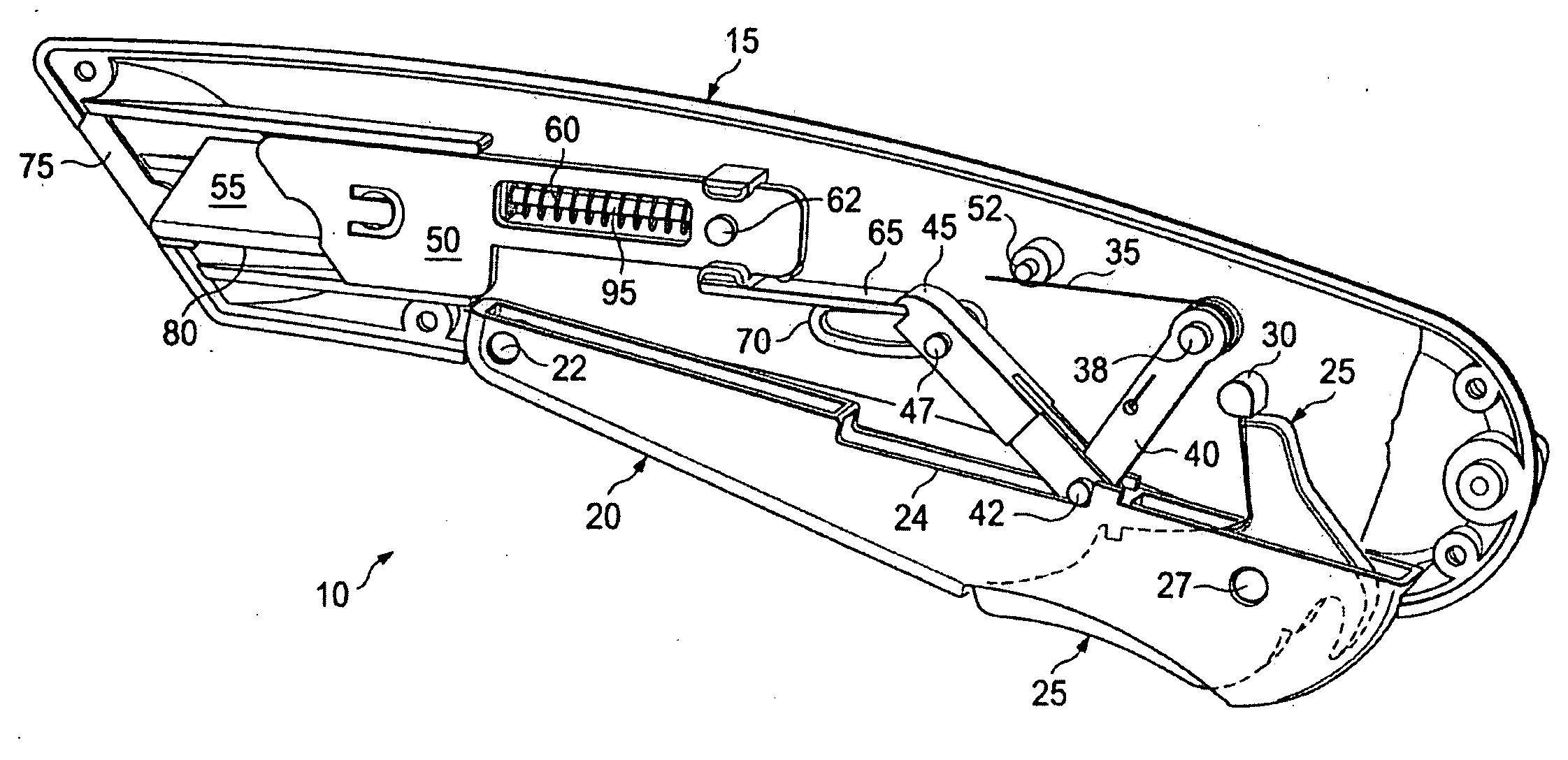
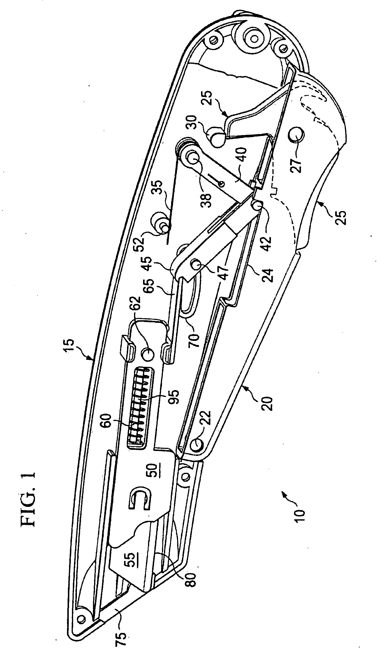
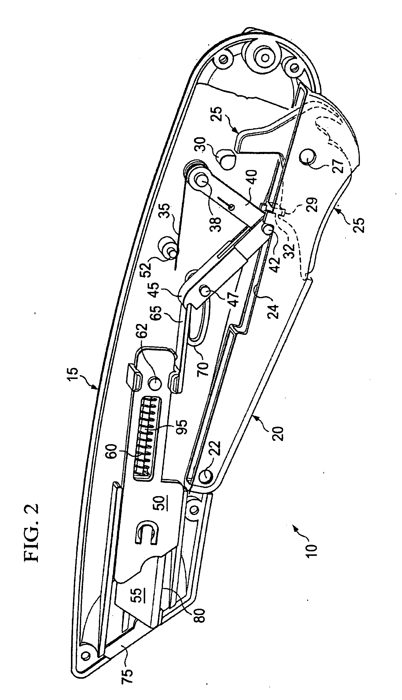
[0023]The figures and following description illustrate and explain a utility cutter 10, which may be used to cut rigid or semi-rigid materials, such as, for example, corrugated board, cardboard or other paper products, rubber, plastic, Styrofoam, or any other appropriate material. The utility cutter 10 is typically a handheld device operated by either a left-handed or right-handed user with equal ease. In some implementations, the utility cutter 10 allows the user to carry, transport, or otherwise handle the cutter 10 in a back position, whereby a sharpened blade of the cutter 10 is locked in a retracted position within a protective housing or handle. The user may, as appropriate, set the cutter 10 into an unlocked position via an integral trigger lock within a blade trigger. Further, the user may, substantially simultaneous to placing the utility cutter 10 into the unlocked position, easily and ergonomically actuate the blade trigger to extend the sharpened blade from the protectiv...


PUM


Abstract

A utility cutter includes a housing, a blade and blade shuttle, a blade trigger, and a trigger lock. The blade and blade shuttle are enclosed within the housing in a retracted position. The blade is extended from the housing in an extended position. The blade trigger includes a cavity and is coupled to the housing. The blade shuttle is conveyed from the retracted position to the extended position when the blade trigger pivots from a rest position to an engaged position. The trigger lock includes a projection and is accessible at the exterior of the housing through the blade trigger. The trigger lock is coupled to the blade trigger and the projection is in contact with the stop pin when the blade shuttle is in the retracted position. The blade trigger is pivotable from the rest position to the engaged position when the projection is released from the stop pin.

Description

TECHNICAL BACKGROUND[0001]This disclosure relates to cutting rigid and semi-rigid materials, and more particularly, to cutting rigid and semi-rigid materials with a utility cutter including an integral trigger lock.BACKGROUND[0002]Utility cutters may be used to cut or slice a variety of materials, such as cardboard, corrugated board of varying thickness, rubber, lightweight plastic, or other packaging material. In order to cut or slice such material, the utility cutter may need to have a sharpened blade. Certain precautions may be used to protect or help protect a user from the sharpened blade. For example, a utility cutter may include guards that extend from the cutter alongside the sharpened blade, such that the guards substantially prevent an accidental injury to the user or other bystander. Further, a utility cutter may include a protective handle that encloses substantially all of a blade during periods of non-use. Utility cutters, however, may be actuated accidentally even dur...

Claims


Application Information

Patent Timeline
IPC IPC(8): B26B1/08
CPCB26B5/003
Inventor DAVIS, RAYMOND E.HAMPTON, CLIFTON GLENN
Owner ADCO IND TECH
Why Eureka
Try Eureka