Heat exchanger

a heat exchanger and heat exchanger technology, applied in the field of heat exchangers, can solve the problems of reducing the attachment location of the heat exchanger, unnecessarily large amount of waste heat, and low thermal conductivity, and achieves the effect of high level of secondary flow components, high heat exchange efficiency, and high efficiency of heat exchang

Active Publication Date: 2010-04-15
THE UNIV OF TOKYO +1
View PDF12 Cites 27 Cited by
  • Summary
  • Abstract
  • Description
  • Claims
  • Application Information

AI Technical Summary

Benefits of technology

[0014]Further, in the heat exchanger in accordance with present invention, each of the multiple heat exchanging tubes may be structured to have the line of sequential wave crests and the line of sequential wave troughs arranged to satisfy inequality that 1.3×Re−0.5<a / p<0.2, where ‘a’ denote an amplitude of a waveform including one wave crest from the line of sequential wave crests and one wave trough from the line of sequential wave troughs, ‘p’ denotes a pitch as an interval between the line of sequential wave crests and the line of sequential wave troughs formed on one face and the line of sequential wave crests and the line of sequential wave troughs formed on an opposed face arranged to be opposite to the one face across a fluid flow, and ‘Re’ denotes a Reynolds number defined by a bulk flow rate and the pitch ‘p’. The heat exchanger of this application enables the eddies of the secondary flows generated in the course of the fluid flow to function as an effective secondary flow component for acceleration of heat transfer without being affected by the opposed wall face across the fluid flow. This arrangement gives the higher-performance, small-sized heat exchanger having the higher efficiency of heat exchange.
[0015]Alternatively, in the heat exchanger in accordance with present invention, each of the multiple heat exchanging tubes may be structured to have the line of sequential wave crests and the line of sequential wave troughs arranged to satisfy inequality that 0.25<W / z<2.0, where ‘W’ denotes the preset interval of the folding lines and ‘z’ denotes a wavelength of a waveform including one wave crest from the line of sequential wave crests and one wave trough from the line of sequential wave troughs. The heat exchanger of this application prevents an increase in ratio of a span direction moving distance of the secondary flow component to a vertical direction distance to an opposed wall face. This arrangement keeps a high level of the secondary flow component effective for acceleration of heat transfer. This arrangement gives the higher-performance, small-sized heat exchanger having the higher efficiency of heat exchange.
[0016]Also, in the heat exchanger in accordance with present invention, each of the multiple heat exchanging tubes may be structured to have the line of sequential wave crests and the line of sequential wave troughs arranged to satisfy inequality that 0.25<r / z, in which ‘r’ denotes a radius of curvature at a top of each wave crest from the line of sequential wave crests and / or at a bottom of each wave trough from the line of sequential wave troughs and ‘z’ denotes a wavelength of a waveform including one wave crest from the line of sequential wave crests and one wave trough from the line of sequential wave troughs. The heat exchanger of this application effectively controls a local speed multiplication of the fluid flow running along the waveforms of the wave crests and the wave troughs. This arrangement desirably prevents an increase of the flow resistance. This arrangement gives the higher-performance, small-sized heat exchanger having the higher efficiency of heat exchange.
[0017]In addition, in the heat exchanger in accordance with present invention, each of the multiple heat exchanging tubes may be structured to have the line of sequential wave crests and the line of sequential wave troughs arranged to have an angle of inclination of not less than 25 degrees on a cross section of a waveform including one wave crest from the line of sequential wave crests and one wave trough from the line of sequential wave troughs. The heat exchanger of this application enhances the secondary flow component along the waveforms of the wave crests and the wave troughs. The enhanced secondary flow component effectively generates the secondary flows contributing to heat transfer and increases an effective area for heat transfer of inclined planes on the cross section of the waveforms of the wave crests and the wave troughs. This arrangement gives the higher-performance, small-sized heat exchanger having the higher efficiency of heat exchange.

Problems solved by technology

This leads to an unnecessarily large amount of waste heat.
The requirement of size reduction limits the attachment location of the heat exchanger.
The stainless steel material with excellent corrosion resistance has relatively low thermal conductivity, so that the stainless steel fins have the lowered efficiency.
The presence of the fins may interfere with the outflow of condensate water and thereby with efficient heat exchange.
Such deformation undesirably increases the flow resistance of the fluid flowing between the flattened tubes and reduces the amount of heat exchange.

Method used


Image

  • Heat exchanger
  • Heat exchanger
  • Heat exchanger

Examples


Embodiment Construction

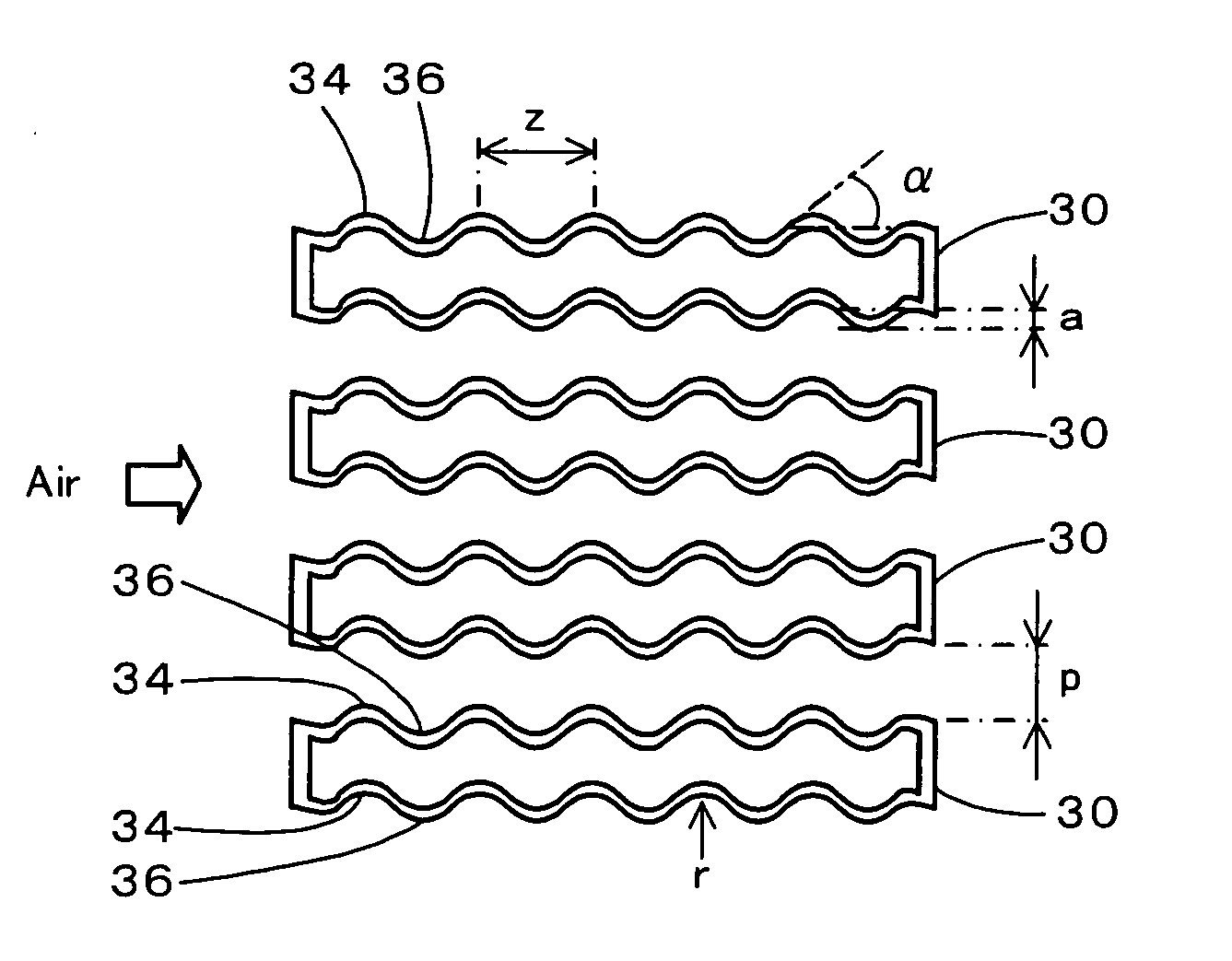
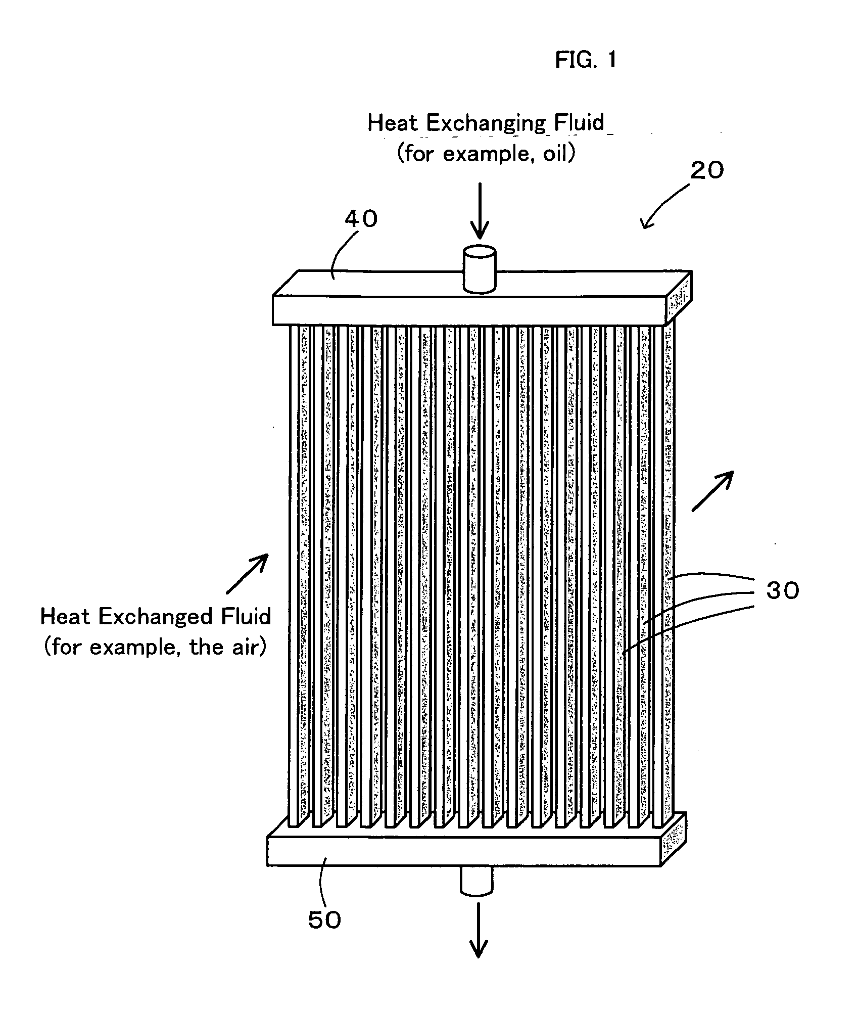
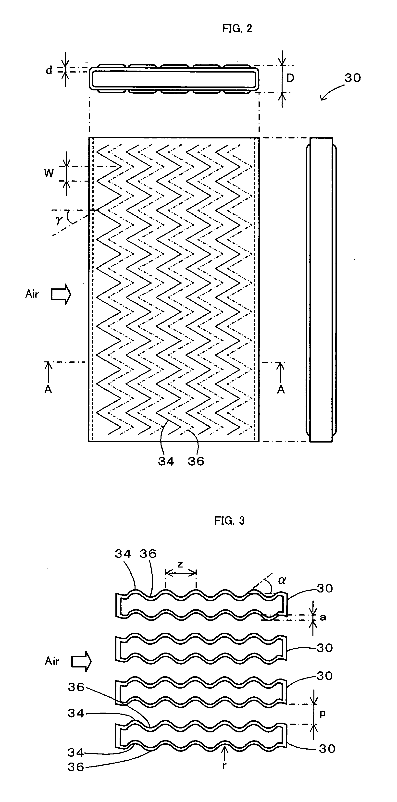
[0032]One mode of carrying out the invention is discussed below as a preferred embodiment with reference to the accompanied drawings. FIG. 1 is an outline view showing the appearance of a heat exchanger 20 in one embodiment of the invention. FIG. 2 is an explanatory view showing a top face, a front face, and a side face of a heat exchanging tube 30 used for the heat exchanger 20 of the embodiment. FIG. 3 is a sectional explanatory view showing A-A cross sections of plurality of the heat exchanging tubes 30 shown in FIG. 2. As illustrated, the heat exchanger 20 of the embodiment includes multiple heat exchanging tubes 30 that are formed as flattened hollow tubes and are arranged in parallel with one another, and a pair of headers 40 and 50 that are provided to cover respective ends of the multiple heat exchanging tubes 30 and to make an inflow and an outflow of a heat exchanging fluid into and from the multiple heat exchanging tubes 30.

[0033]Each of the heat exchanging tubes 30 is fo...


PUM


Abstract

A heat exchanger assembled from multiple heat exchanging tubes. Each of the multiple heat exchanging tubes is formed as a flattened tube of 0.5 mm in thickness by press work or bending work of a stainless steel plate member having a thickness of 0.1 mm. Each of the multiple heat exchanging tubes is structured to have multiple lines of sequential wave crests and multiple lines of sequential wave troughs formed on each of flattened faces of the heat exchanging tube. The multiple lines of the sequential wave crests and the multiple lines of the sequential wave troughs are arranged to have a preset angle γ relative to a main stream of an air flow. The lines of the sequential wave crests and the lines of the sequential wave troughs are symmetrically folded back about folding lines arranged at a preset interval W along the main stream of the air flow.

Description

TECHNICAL FIELD[0001]The present invention relates to a heat exchanger, and more specifically pertains to a heat exchanger designed to have multiple heat exchanging tubes, which are made of a thermally conducting material, are formed as hollow tubes of a flattened cross section, and are arranged in parallel with one another, and configured to cool down or heat up a heat exchanging fluid through heat exchange between the heat exchanging fluid flowing inside the multiple heat exchanging tubes and a heat exchanged fluid flowing between the multiple heat exchanging tubes.BACKGROUND ART[0002]One proposed structure of the heat exchanger has multiple tubes arranged to make circulation of a refrigerant between a refrigerant inlet tank and a refrigerant outlet tank and thereby perform heat exchange with the outside air (see, for example, Japanese Patent Laid-Open No. 2001-167782). In the heat exchanger of this prior art structure, as the refrigerant introduced into the inlet tank flows in th...

Claims


Application Information

Patent Timeline
Patent Type & Authority Applications(United States)
IPC IPC(8): F28F1/10
CPCF28D1/05366F28F1/06F28F1/08F28F1/10F28F1/16F28F13/06F28F1/38F28F1/40F28F1/42F28F1/426F28F3/046F28F1/34
Inventor SHIKAZONO, NAOKIWAKE, TSUNEHITOIKUTA, SHIRO
Owner THE UNIV OF TOKYO
Why Eureka
Try Eureka