Method and device for easily monitoring the maintenance status of an uv-drinking water disinfection system in an aircraft

Active Publication Date: 2010-04-15
AIRBUS OPERATIONS GMBH
View PDF9 Cites 14 Cited by
  • Summary
  • Abstract
  • Description
  • Claims
  • Application Information

AI Technical Summary

Benefits of technology

[0031]The radiation intensities determined by the evaluation unit may also be recorded. The maintenance time consequently may be determined based on the resulting diagram. A periodic maintenance within fixed time intervals consequently may be eliminated.
[0041]This warning device may also be coupled to a shut-off mechanism, for example, for the water supply such that the delivery of drinking water that may possibly be contaminated with pathogenic microorganisms may be prevented.
[0048]The central idea of the invention consists of respectively eliminating the attenuation influence of a liquid to be disinfected on the light emitted by a UV-radiator from an overall absorption by, e.g., two UV-sensors in a different geometric configuration in order to subsequently deduce the currently emitted UV-radiation intensity that may possibly be diminished due to deposits and radiator aging.

Problems solved by technology

Cell division and progeny are now no longer possible.
These water ingredients may also soil the UV-disinfection system or lead to deposits on the cladding tubes.
Particularly in the mobile use of UV-disinfection systems such as, for example, in aircraft, buses, rail vehicles or ships that obtain the drinking water intended for disinfection from different sources, reliable information on the maintenance status of the UV-radiator / cladding combination may usually not be obtained based on a measured value of a UV-sensor due to the changing UV-transmittance of the drinking water.

Method used


Image

  • Method and device for easily monitoring the maintenance status of an uv-drinking water disinfection system in an aircraft
  • Method and device for easily monitoring the maintenance status of an uv-drinking water disinfection system in an aircraft
  • Method and device for easily monitoring the maintenance status of an uv-drinking water disinfection system in an aircraft

Examples


Embodiment Construction

[0061]It should first be mentioned that identical components are identified by the same reference symbols in the figures and that the drawings are merely schematic and not necessarily true-to-scale.

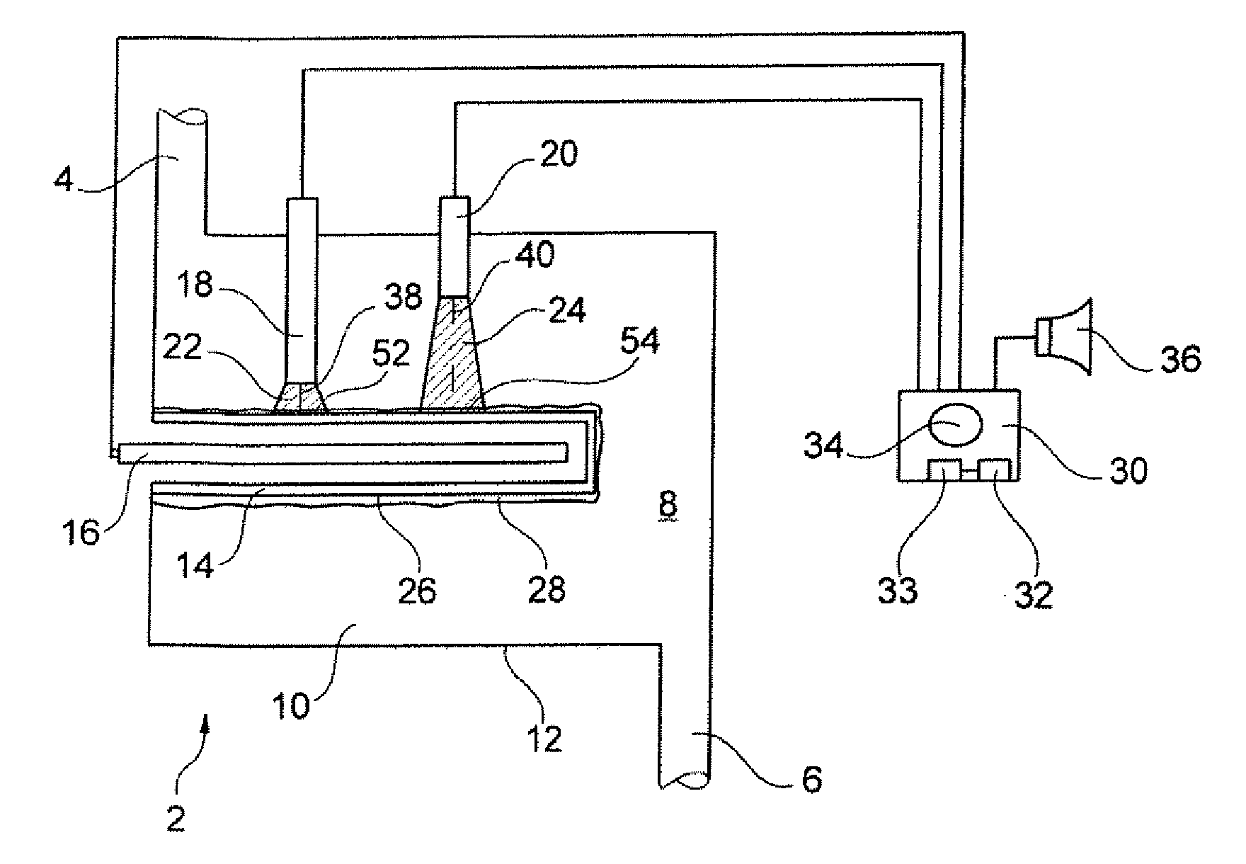
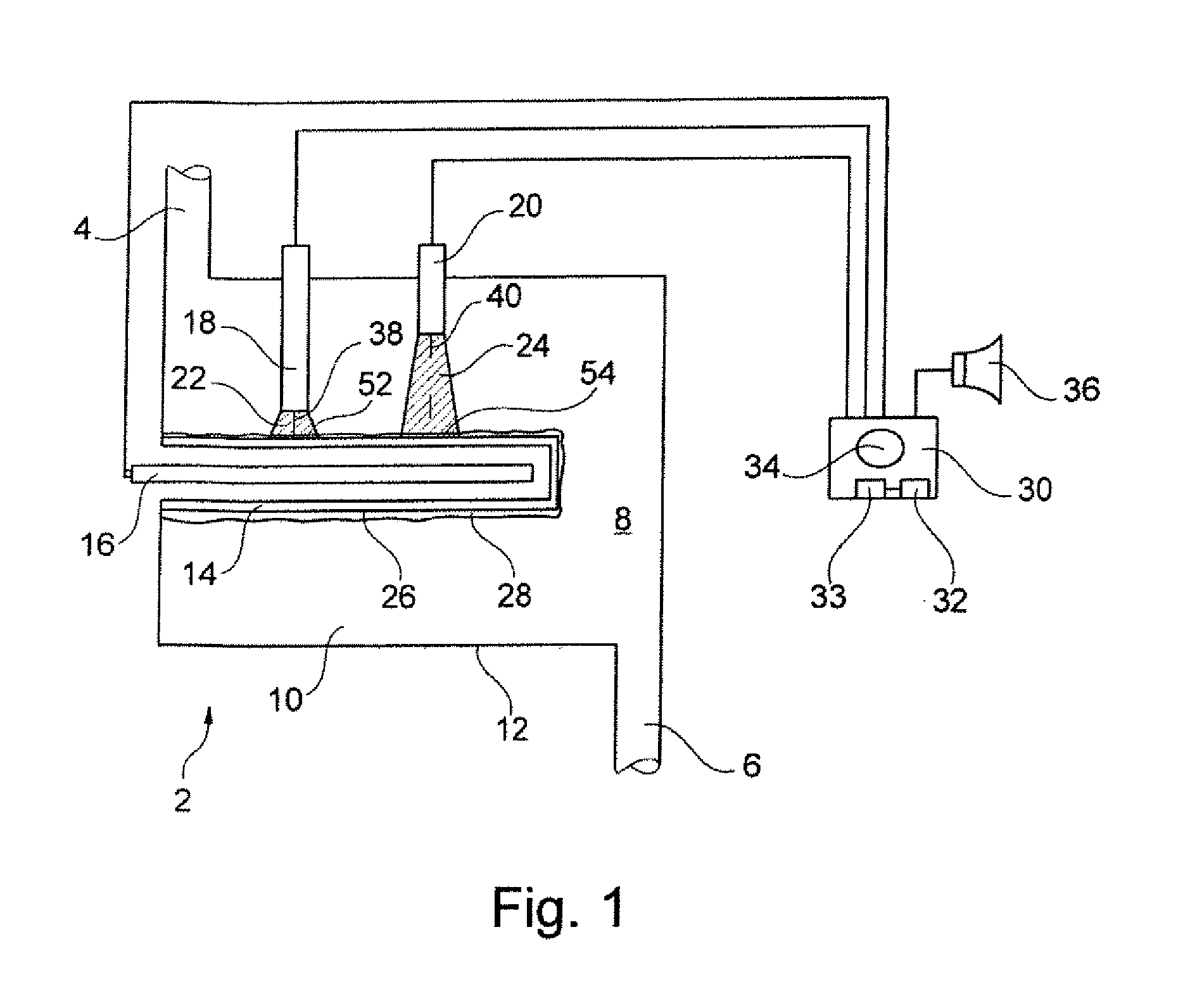
[0062]FIG. 1 shows a schematic representation of an inventive disinfection system 2 with an inlet 4 and an outlet 6 for liquids 8 to be disinfected. In the present embodiment, the liquid 8 to be disinfected consists of drinking water. The disinfection system 2 comprises an irradiation chamber 10 that is surrounded by a wall 12 that is impervious to UV-light. A cladding 14 of UV-transparent silica glass is arranged in the irradiation chamber 10, wherein the UV-radiator 16 is situated in said cladding. Furthermore, a first 18 and a second UV-sensor 20 are arranged in the irradiation chamber 10 in such a way that the first UV-sensor 18 is spaced apart from the cladding 14 by a first distance 38 and has a first conical range of vision 22 and the second UV-sensor 20 is spaced apart from the cl...


PUM


Abstract

A disinfection system for liquids is provided that features an irradiation chamber for accommodating a liquid to be disinfected. A UV-radiator with a cladding that is transparent to UV-light is arranged in the irradiation chamber such that the UV-radiation emitted by the UV-radiator may penetrate the liquid. A first UV-sensor is arranged in the irradiation chamber such that a first attenuation characteristic with respect to the UV-light emitted by the UV-radiator may be measured with the first UV-sensor, wherein the first attenuation characteristic comprises a first aging characteristic and a first liquid attenuation characteristic. A second UV-sensor is arranged in the irradiation chamber such that a second attenuation characteristic with respect to the UV-light emitted by the UV-radiator may be measured with the second UV-sensor, wherein the second attenuation characteristic comprises a second aging characteristic and a second liquid attenuation characteristic and differs from the first attenuation characteristic.

Description

CROSS-REFERENCE TO RELATED APPLICATIONS[0001]This application claims the benefit of the filing date of U.S. Provisional Patent Application No. 61 / 195,830 filed Oct. 10, 2008, the disclosure of which is hereby incorporated herein by reference.FIELD OF THE INVENTION[0002]The present invention relates to a disinfection system for liquids that is based on UV-radiation. Particularly, the invention relates to a disinfection system for liquids, a method for disinfecting liquids and an aircraft with a disinfection system.BACKGROUND OF THE INVENTION[0003]Disinfecting means killing or inactivating pathogenic organisms and may be achieved by UV-irradiation in the wavelength range between 200 and 300 nm. Pathogenic microorganisms may cause diseases, particularly in humans. The germicidal effect of short-wave UV-radiation is based on the absorption of this radiation by nucleic acids (DNA, RNA) in the cell nucleus of the microorganisms. UV-radiation in the wavelength range of approximately 260 nm...

Claims


Application Information

Patent Timeline
IPC IPC(8): G08B17/12B01J19/12
CPCB64D11/02C02F1/325C02F2201/001C02F2303/04C02F2201/326C02F2209/006C02F2201/3225
Inventor SCHREINER, AXEL
Owner AIRBUS OPERATIONS GMBH
Why Eureka
Try Eureka